This article applies to Solis residential low voltage hybrid inverters paired with integrated APsmart transmitters and TT Solar JMS-PS1(B) string-level rapid shutdown receivers.
Applicable Solis Models:
- S6-EH2P9.6K03-SV-YD-L-US
- S6-EH2P11.4K03-SV-YD-L-US
- S6-EH2P12K03-SV-YD-L-US
- S6-EH2P14K03-SV-YD-L-US
- S6-EH2P16K03-SV-YD-L-US
The purpose of this article is to explain how the UL 3741 PV Hazard Control System pathway lets Solis residential PV systems substitute string-level rapid shutdown (SLRSD) equipment for module-level rapid shutdown (MLRSD). It defines the certification distinctions between PVRSE, PVRSS, and PVHCS, describes the SunSpec PLC signaling architecture Solis uses to control third-party SLRSD receivers, lists the approved equipment pairings for the Solis S6-EH2P(9.6-16)K-SV-YD-L-US hybrid inverter series in North America, and provides installation instructions drawn from the Solis and TT Solar manuals. Throughout this document, "S6-EH2P" is shorthand for the full inverter series designation.
Common Acronyms
Term | Meaning |
CRD | Certification Requirement Decision (UL) |
DER | Distributed Energy Resource |
MLRSD | Module-Level Rapid Shutdown |
MPPT | Maximum Power Point Tracker |
NEC | National Electrical Code (NFPA 70) |
NRTL | Nationally Recognized Testing Laboratory |
PLC | Power Line Communication |
PVHCS | Photovoltaic Hazard Control System |
PVRSE | Photovoltaic Rapid Shutdown Equipment |
PVRSS | Photovoltaic Rapid Shutdown System |
RSD | Rapid Shutdown |
SLRSD | String-Level Rapid Shutdown |
1. What is UL 3741 and how does it enable string-level rapid shutdown (SLRSD)?
1.1 The standard
UL 3741, Standard for Photovoltaic Hazard Control, was first published by Underwriters Laboratories on December 8, 2020 and was updated in October 2025. It is referenced in the 2020 and 2023 editions of the National Electrical Code (NEC) at Section 690.12(B)(2)(1) as one of the accepted pathways for satisfying rapid shutdown requirements inside the PV array boundary.
The standard evaluates the design of PV Hazard Control Systems (PVHCS) which includes the combination of PV modules, wiring, combiners, inverters, racking, and other PV array-mounted equipment, such as rapid shutdown receivers and initation devices (transmitters), to determine whether the assembled PV array poses a shock hazard to firefighters in an emergency. Certification is granted at the system level by a Nationally Recognized Testing Laboratory (NRTL) once the entire assembly has been shown to keep firefighters out of hazardous current paths.
1.2 How UL 3741 changes the rules inside the PV boundary
NEC 690.12(B) defines the PV array boundary as one foot from the PV array in all directions. Prior to UL 3741, the code inside that PV boundary required controlled conductors to be reduced to 80 V or less within 30 seconds of rapid shutdown initiation, which in practice forced the use of module-level rapid shutdown (MLRSD) equipment on every module.
Module-Level Rapid Shutdown (The Old Way)
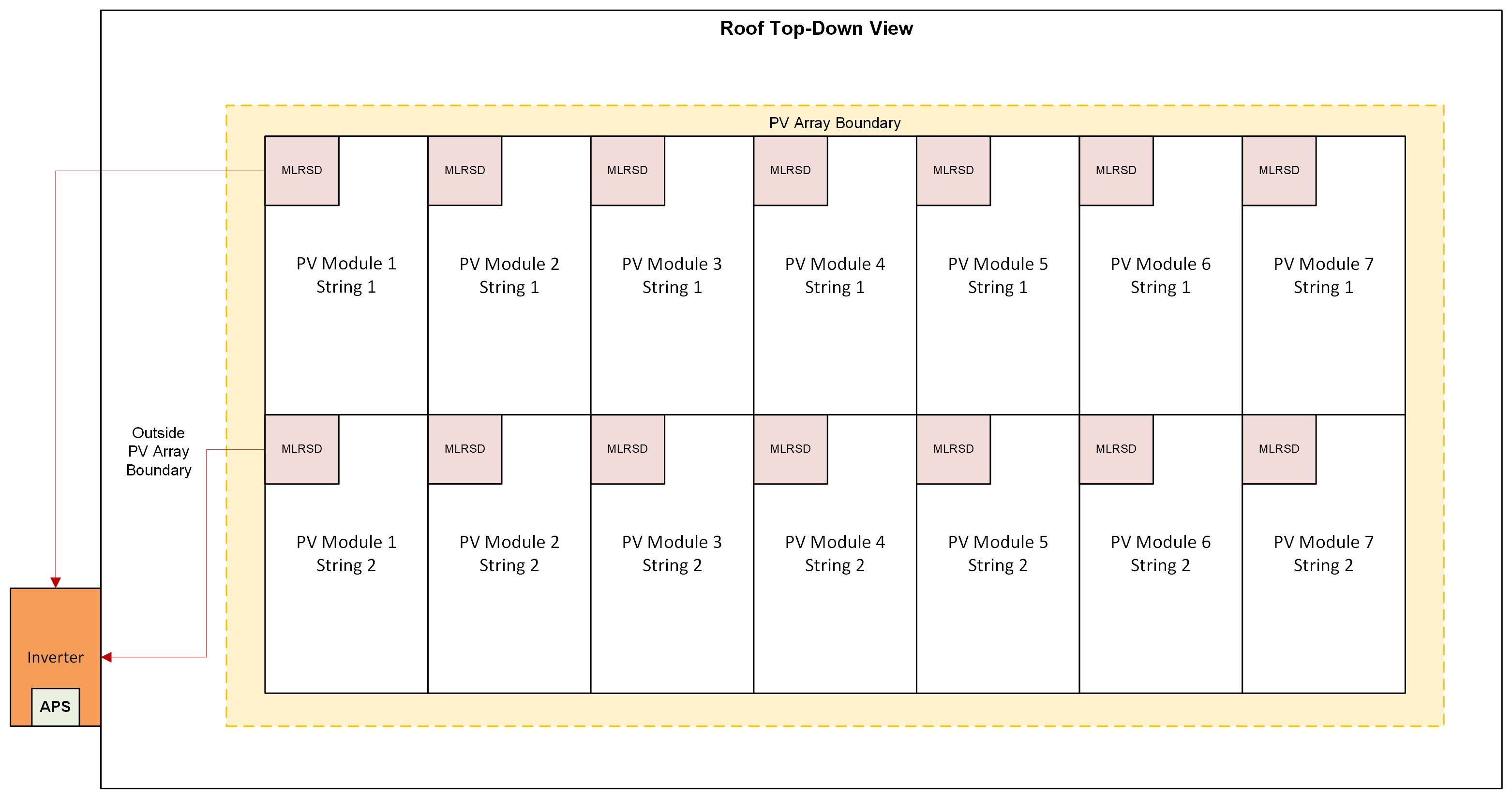
Zoomed-in view of the bottom-left corner of the roof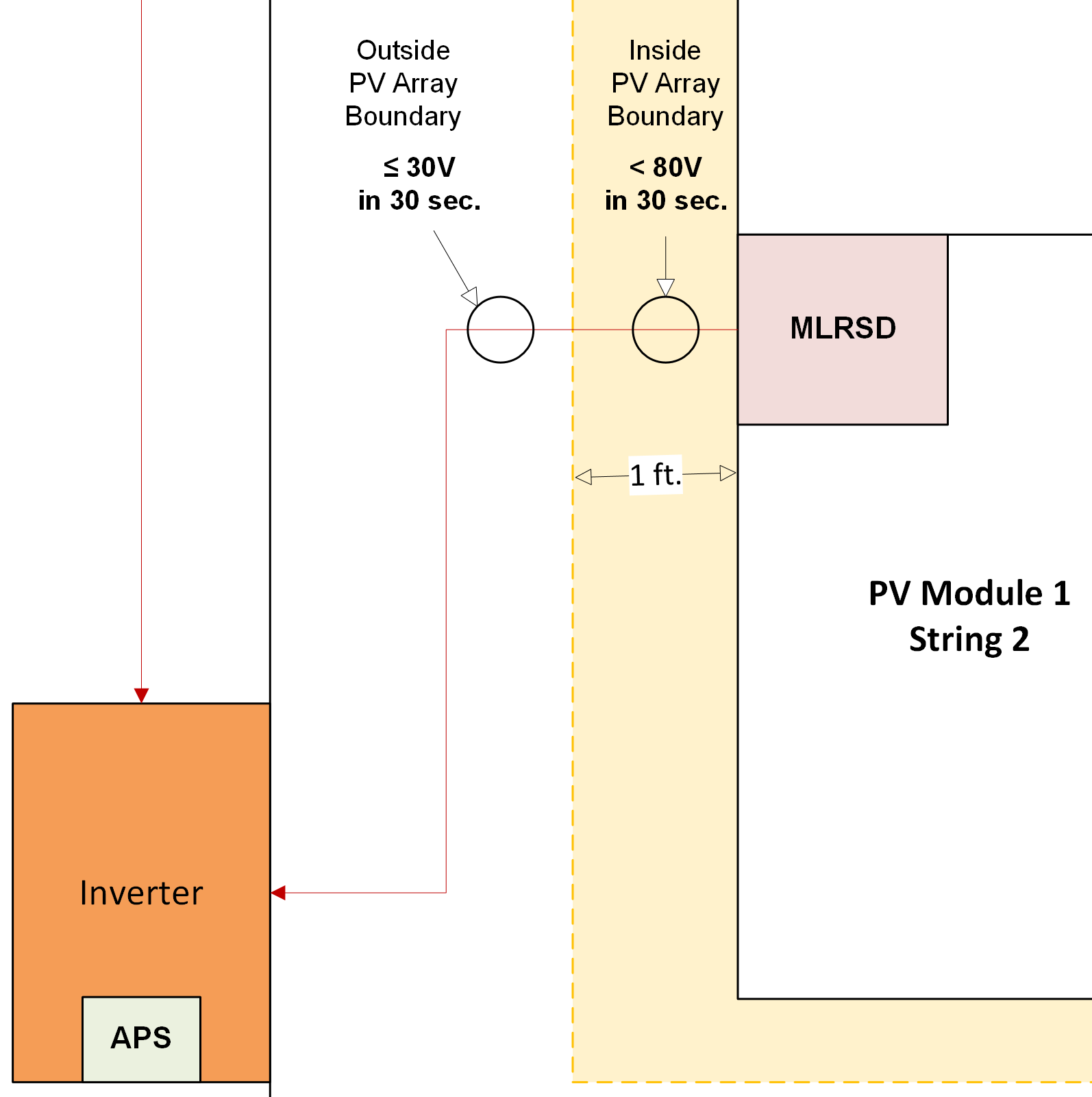
Under NEC 690.12(B)(2)(1), a listed UL 3741 PV Hazard Control System is now an accepted alternative. The rationale is that if the racking manufacturer, working with the module manufacturer, inverter manufacturer, and NRTL, can prove that a firefighter falling onto or through the PV array is not exposed to a shock hazard, the 80 V internal limit no longer applies. DC voltage inside the PV boundary can remain at up to 600 V or 1000 V, depending on the specific PVHCS certificate. Some UL 3741 PVHCS listings on the market today use a 165 V internal threshold rather than 600 V or 1000 V, which lets those systems certify against a wider range of racking configurations. The specific number is not what matters, the point is that once UL 3741 is used, 80 V is no longer the requirement for within the PV array boundary. Each PVHCS listing defines its own internal voltage limit based on the NRTL evaluation of that specific PV array, racking, and inverter combination.
The rule outside the PV boundary is unchanged. Controlled conductors located more than one foot from the PV array, or more than three feet from the point of entry inside a building, must still be reduced to 30 V or less within 30 seconds of rapid shutdown initiation. Because residential inverters are almost always mounted on a wall, in a garage, or on the ground, the inverter is well outside the one-foot PV boundary. An initiator, plus a means of controlling the DC voltage on the home-run conductors between the PV array and the inverter, is still required.
String-Level Rapid Shutdown (The New Way with UL 3741)
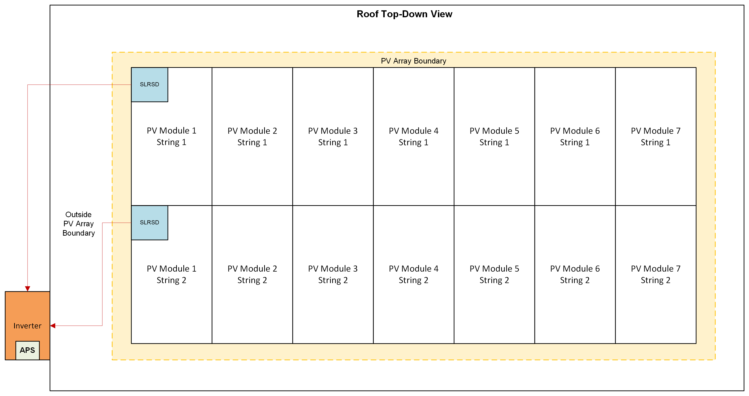
Zoomed-in view of the bottom-left corner of the roof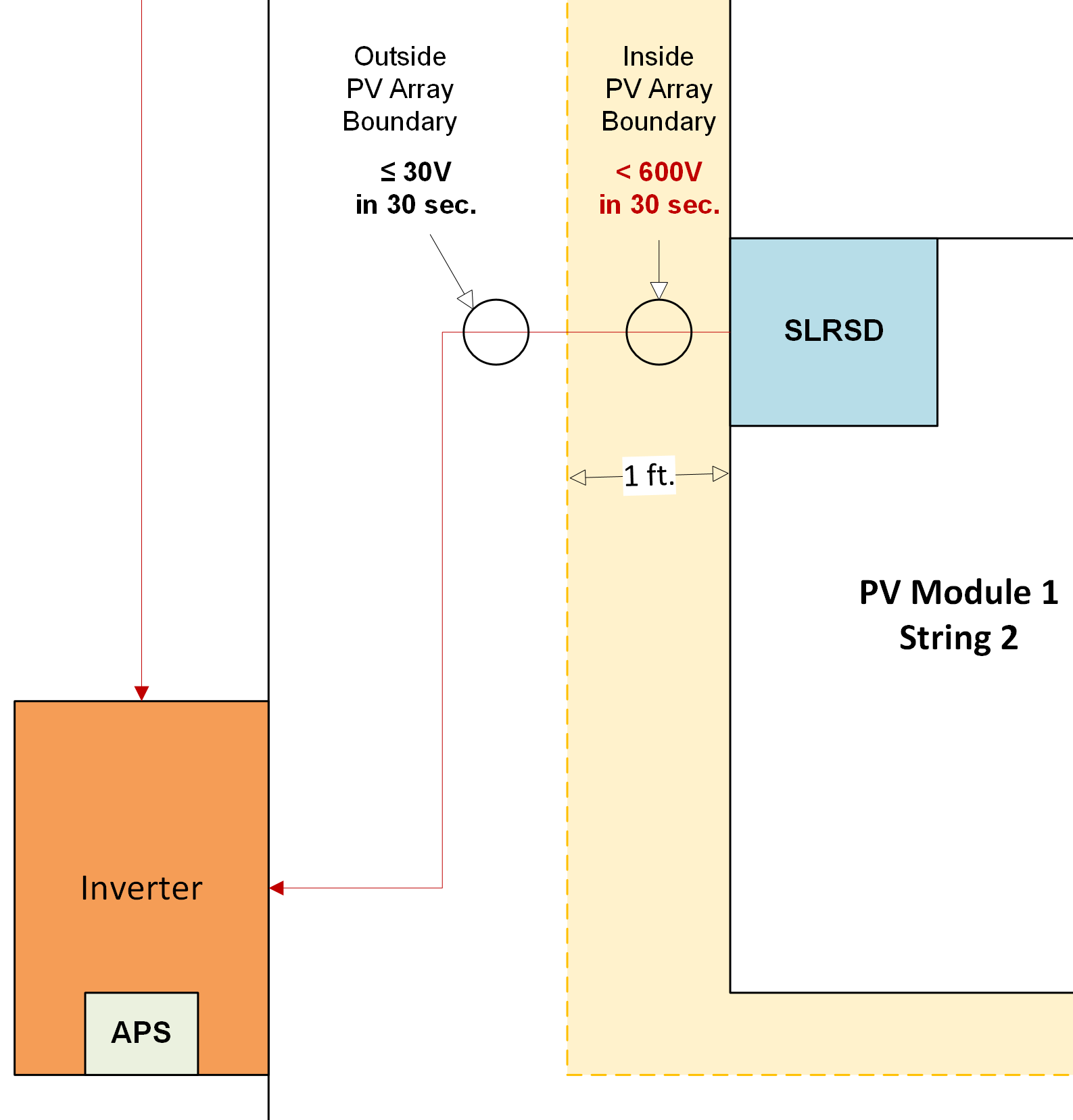
The string-level rapid shutdown (SLRSD) device is what satisfies the 30V or less outside the PV boundary rule under UL 3741. One SLRSD receiver is installed per PV string, at the edge of the PV array under a module connected to the home-run leads going back to the inverter. When the inverter has its rapid shutdown initiation switch pressed, or an external initiator is engaged, the internal APS transmitter stops sending the keep-alive PLC signal down the DC leads to the SLRSD receivers. The receivers open within 30 seconds, isolating the home-run conductors and dropping their voltage to below 30V outside of the PV array boundary. Each SLRSD receiver has a safety voltage of about 4.7V regardless of how many PV modules are connected in series to it.
This presents a substantial reduction in rooftop equipment compared to module-level RSD. A typical residential system with 40 modules requires up to 40 individual MLRSD receivers under the traditional pathway. Under UL 3741 with SLRSD, the same system uses one SLRSD receiver per PV string, often two or three total for the whole system. The inverter can connect to six PV strings maximum, which means six SLRSD devices total per inverter.
1.4 TT Solar String-Level RSD Device JMS-PS1(B)
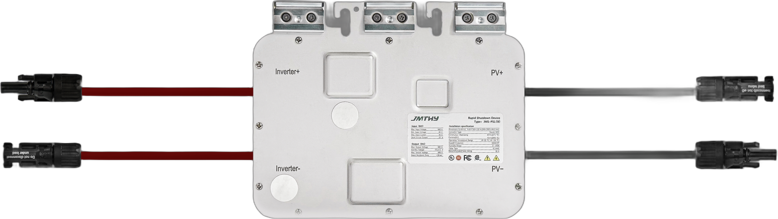
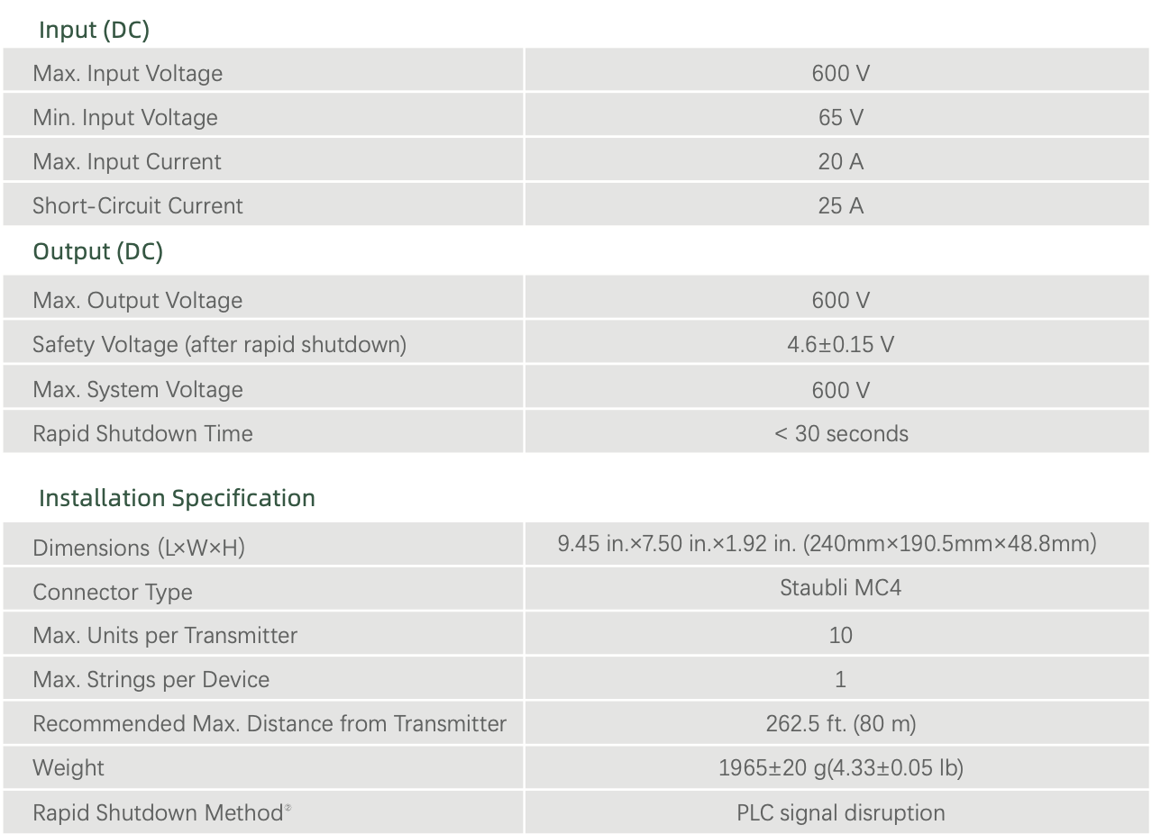
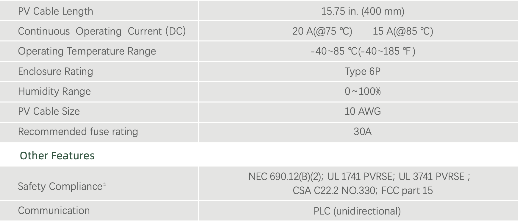
TT Solar is a partner of Solis who is the OEM for the JMS-PS1(B) string-level RSD device. This device is UL 1741 CRD PVRSE-certified and UL 1741 CRD PVRSS-certified with Solis S6-EH2P models and the APS transmitter. To have a UL 3741 compliant system using Solis requires the installation of these SLRSD devices within the PV array.
1.5 What value does string-level RSD and UL 3741 bring to the system owner?
Aside from being safer to firefighters, UL 3741 systems utilizing string-level rapid shutdown instead of module-level rapid shutdown can experience a cost savings as well.
UL 3741 controlled-array certification with string-level RSD (one transmitter core per string, one receiver per string) removes the need for a rapid-shutdown device at every module. Compared with module-level rapid shutdown (MLPE-based RSD, optimizers, or microinverters), this benefits both owner and installer.
Value to the System Owner
Lower system cost. Fewer devices and less installation time means less total system cost for the owner of the system.
Far fewer failure points. A 48-module array with module-level RSD has 48 active rooftop receivers, plus 48 added connector pairs and attachment points under the array. String-level RSD replaces that with a maximum of 6 receivers. Module-level architectures have been shown to multiply potential points of failure by a factor of two to three over string-level designs.
Less lost production. Most MLPE field failures are connector faults and PLC dropouts. If one or two devices fails, it may not be noticed for a while or may not be worth the service providers time to send out a tech to replace just one or two devices. If a string-level device fails, it will be quickly noticed and fixed.
Value to the Installer
Lower system cost. Fewer devices and less installation time means less total system cost to charge the customer (owner) meaning more revenue compared to using module-level RSD.
Faster installation. Installing one device per string vs one device per PV module leads to quicker system builds and less complexity for the installer overall.
Simpler stocking and fewer callbacks. One transmitter and one receiver model cover the array regardless of module count, and lower rooftop device count means fewer warranty truck rolls over the system life. Stocking fewer components in the warehouse and sending installers out with fewer devices.
2. PVRSE, PVRSS, and UL 3741
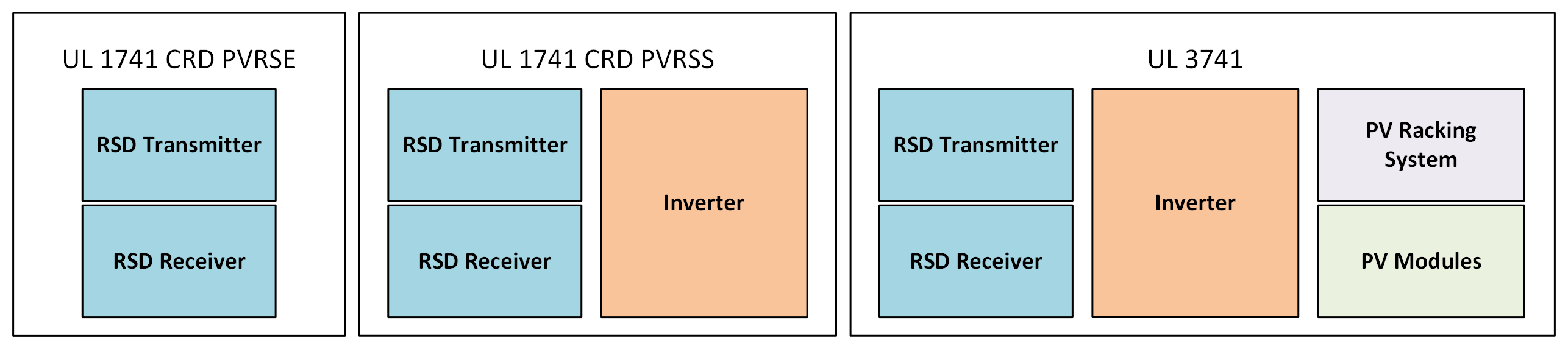
The terms PVRSS, PVRSE, and PVHCS refer to related but distinct certifications. Understanding the differences is essential for specifying, selling, and installing a compliant system. Solis has UL 1741 CRD PVRSS with APS transmitter and TT Solar SLRSD receiver. Intertek approved Solis with APS and TT Solar to be added to the UL 3741 addendum of IronRidge.
2.1 Standard Definitions & Certified Equipment
Acronym | Full name | Certification | Equipment Certified | What it Certifies |
PVRSE | Photovoltaic Rapid Shutdown Equipment | UL 1741 (CRD) PVRSE | RSD receiver (TT) RSD transmitter (APS) | A single piece of equipment intended to initiate, disconnect, isolate, or attenuate controlled conductors of a PV system. Certified independently of any other equipment. |
PVRSS | Photovoltaic Rapid Shutdown System | UL 1741 (CRD) PVRSS | PV inverter RSD receiver RSD transmitter | A tested combination of equipment typically consisting of an inverter, a PLC transmitter, and RSD receivers evaluated together as a system that performs rapid shutdown per NEC 690.12. |
PVHCS | Photovoltaic Hazard Control System | UL 3741 PVHCS | PV racking system PV module PV inverter RSD receiver RSD transmitter | A tested assembly of PV modules, racking, wiring, and equipment evaluated to prove the PV array itself does not expose firefighters to shock hazards, enabling voltages above 80 V inside the PV boundary. The inverter and RSD equipment are considered in the evaluation. Once approved, the inverter models are then added to the racking OEM's UL 3741 addendum. |
3. How string-level rapid shutdown (SLRSD) is accomplished with Solis inverters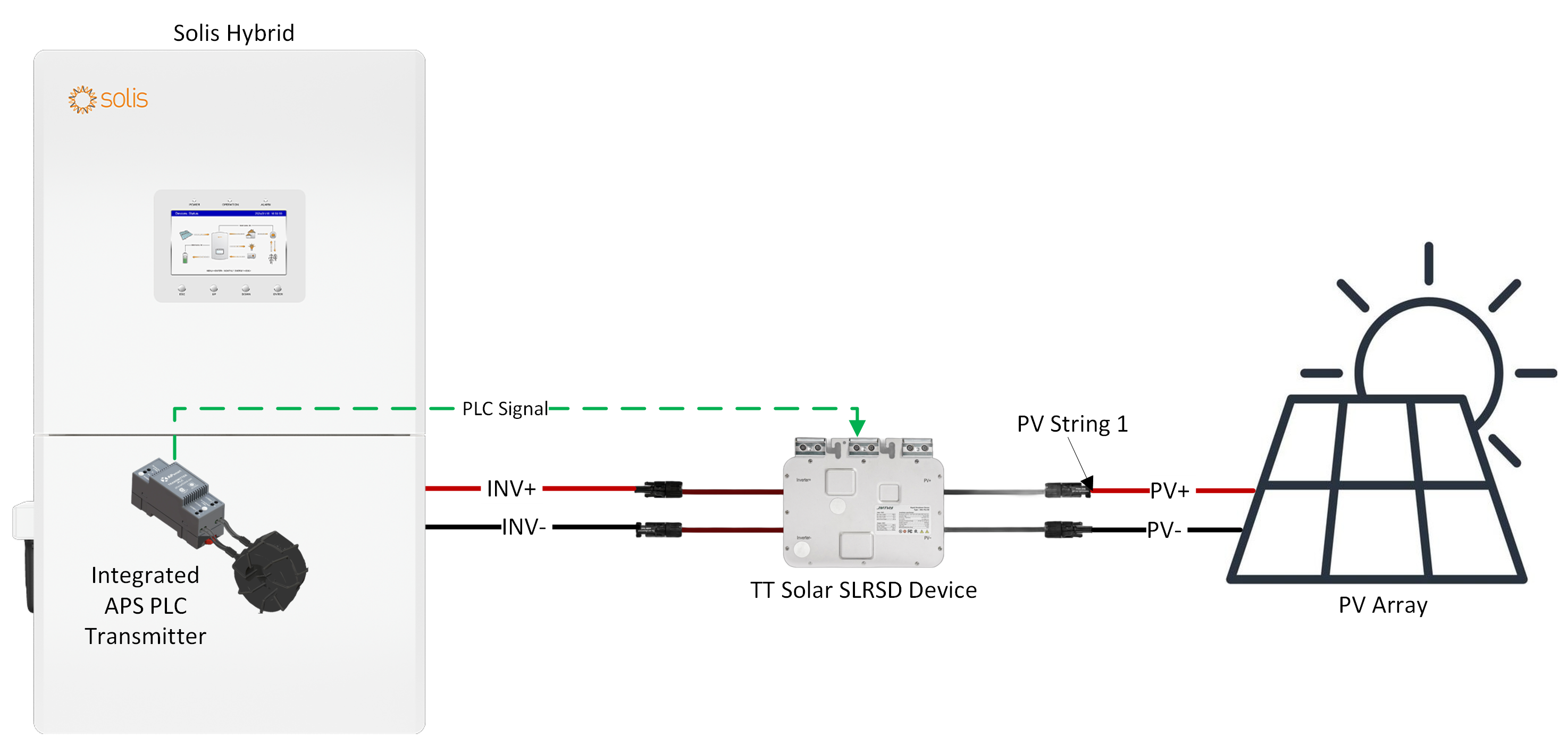
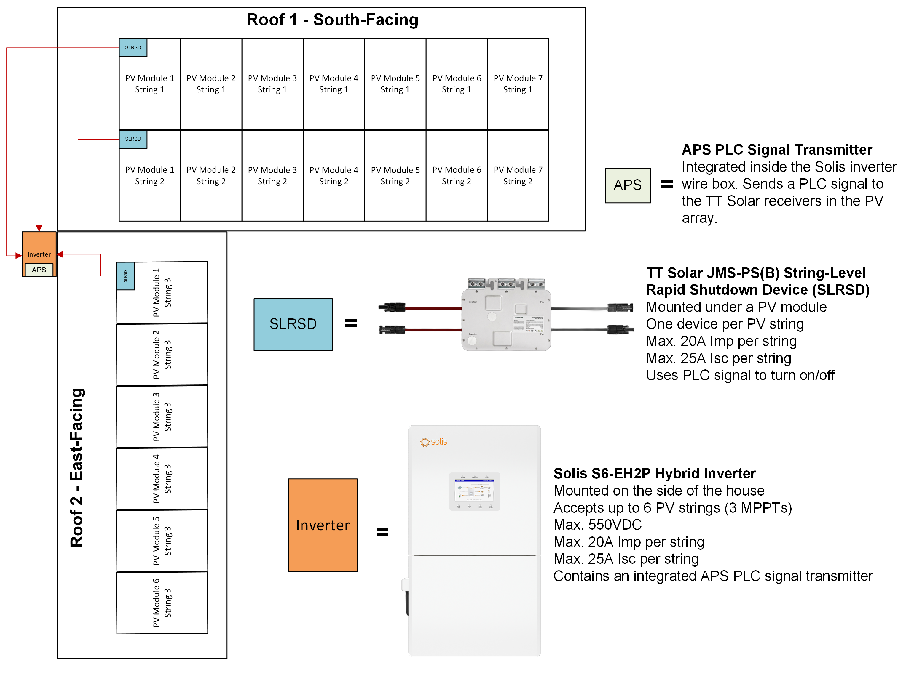
Note: Up to six (6) TT Solar SLRSD devices can be connected to one inverter. The inverter supports a maximum of six (6) PV strings and each string gets only one (1) SLRSD device.
3.1 One SLRSD device per PV string
Solis achieves string-level rapid shutdown by installing one SLRSD receiver on the home-run leads of each PV string, ideally underneath the PV array or at the PV array edge where the device is accessible for service without lifting modules. The device sits between the PV string and the DC input of the inverter, on the two DC conductors carrying the string current.
The Solis inverter itself acts as the rapid shutdown initiator and transmitter. Under UL 3741 there is no separate transmitter cabinet, no separate control wiring, and no low-voltage signal cabling between the inverter and the SLRSD device.
3.2 SunSpec PLC signaling
Communication between the Solis inverter and the SLRSD receivers uses the SunSpec Alliance Communication Signal for Rapid Shutdown, a Power Line Communication (PLC) protocol standardized in 2017 and revised through 2021. The transmitter continuously sends a "permission to operate" keep-alive bit sequence down the DC conductors that are already carrying PV current. Each certified receiver watches for the presence of the keep-alive signal and closes only while the signal is being received.
3.3 How RSD works for the full system
The Solis S6-EH2P inverter must be ordered with the -APST suffix, which specifies the factory-integrated APsmart Transmitter-PLC. Up to x6 TT Solar SLRSD receivers can go with each Solis inverter and integrated APS transmitter that comes factory-installed inside the inverter wire box.
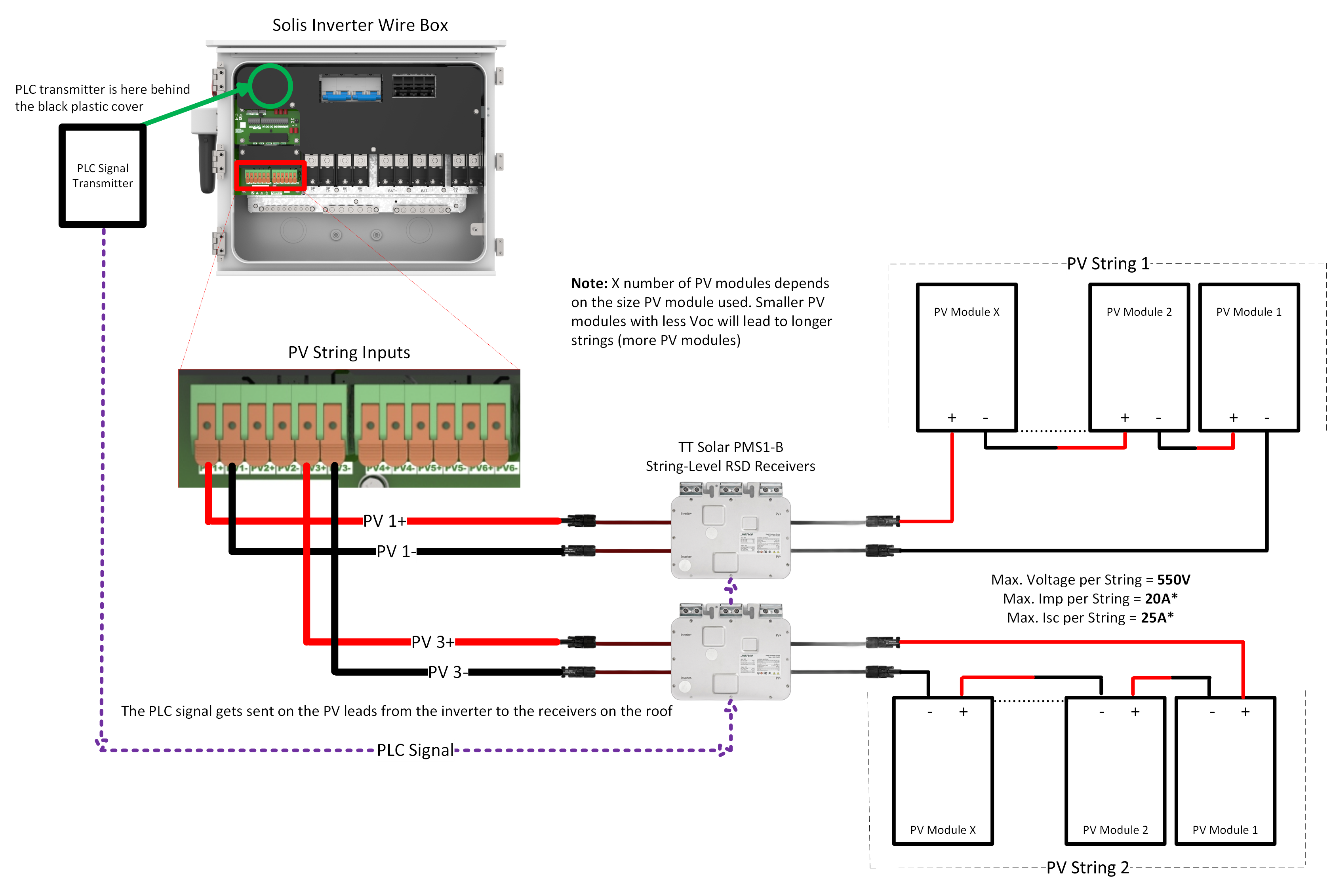
1. The APsmart transmitter continuously sends the PLC keep-alive signal down the PV leads from the inverter to the TTSolar SLRSD receivers on the roof while the inverter is energized.
2. Each TT Solar JMS-PS1(B) SLRSD receiver gets installed on the home-run leads of one PV string within the PV array. Ideally, the receivers get installed at the edge of the array easily accessible to technicians. As long as the inverter is on and the transmitter is sending the PLC signal, the TT Solar receivers will remain on and allow full PV string voltage to pass to the inverter.
4. A rapid shutdown event stops the keep-alive signal. Initiation of the rapid shutdown switch on the inverter will disable the internal APS transmitter and stop the PLC signal to the TT Solar receivers.
5. The JMS-PS1(B) receivers open within 30 seconds. The home-run conductors between the PV array and the inverter drop below 30 V. The DC voltage inside the PV boundary remains at whatever the module strings produce, which is safe because the PV array as a whole is certified under UL 3741 to be safe to firefighters.
6. Disengaging the rapid shutdown switch on the side of the inverter restores power to the internal APS transmitter and allows the PLC signal to once again reach the TT Solar receivers. The PV string voltages come back up to normal.
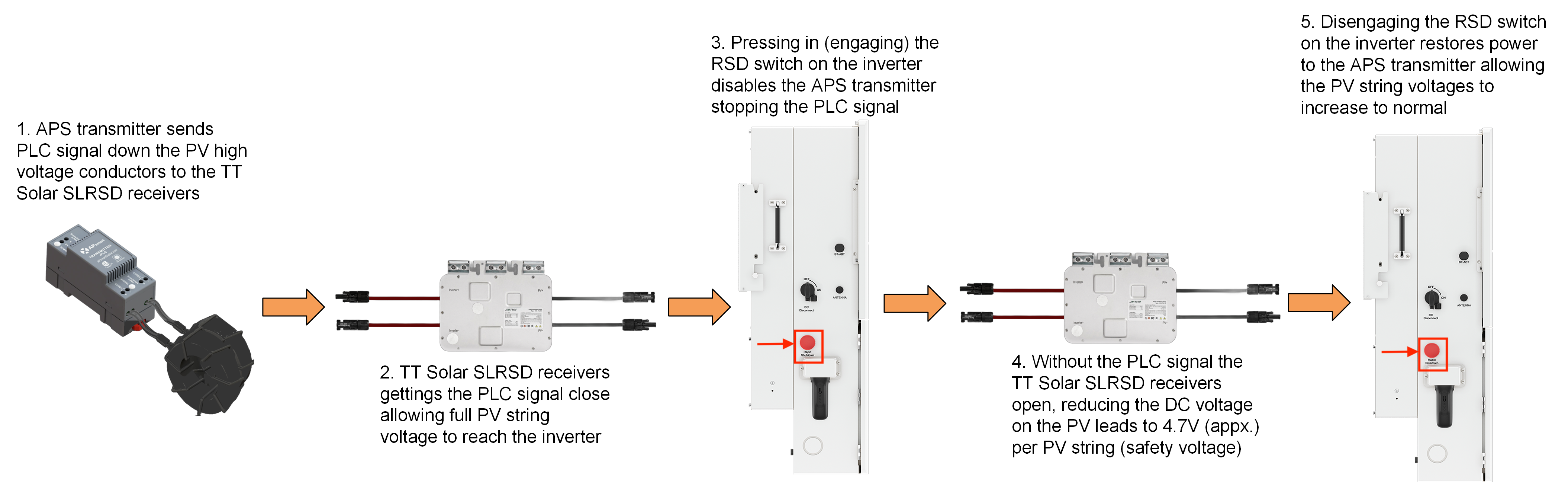
3.4 System diagram
4. Non-Contiguous Arrays
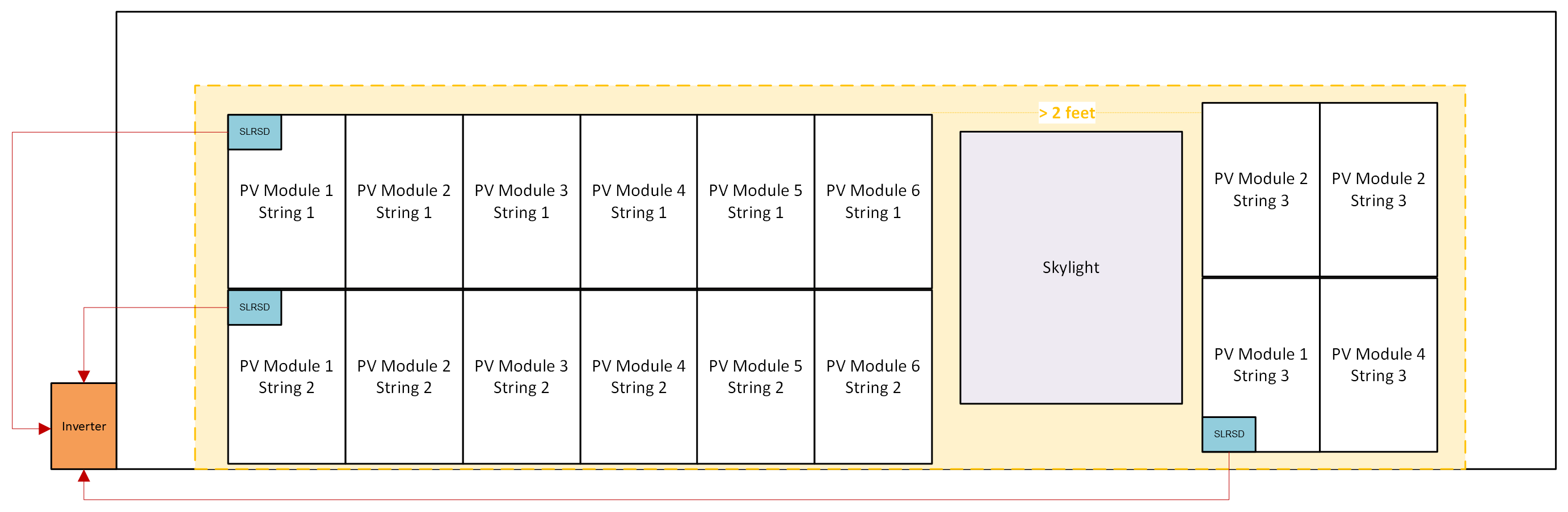
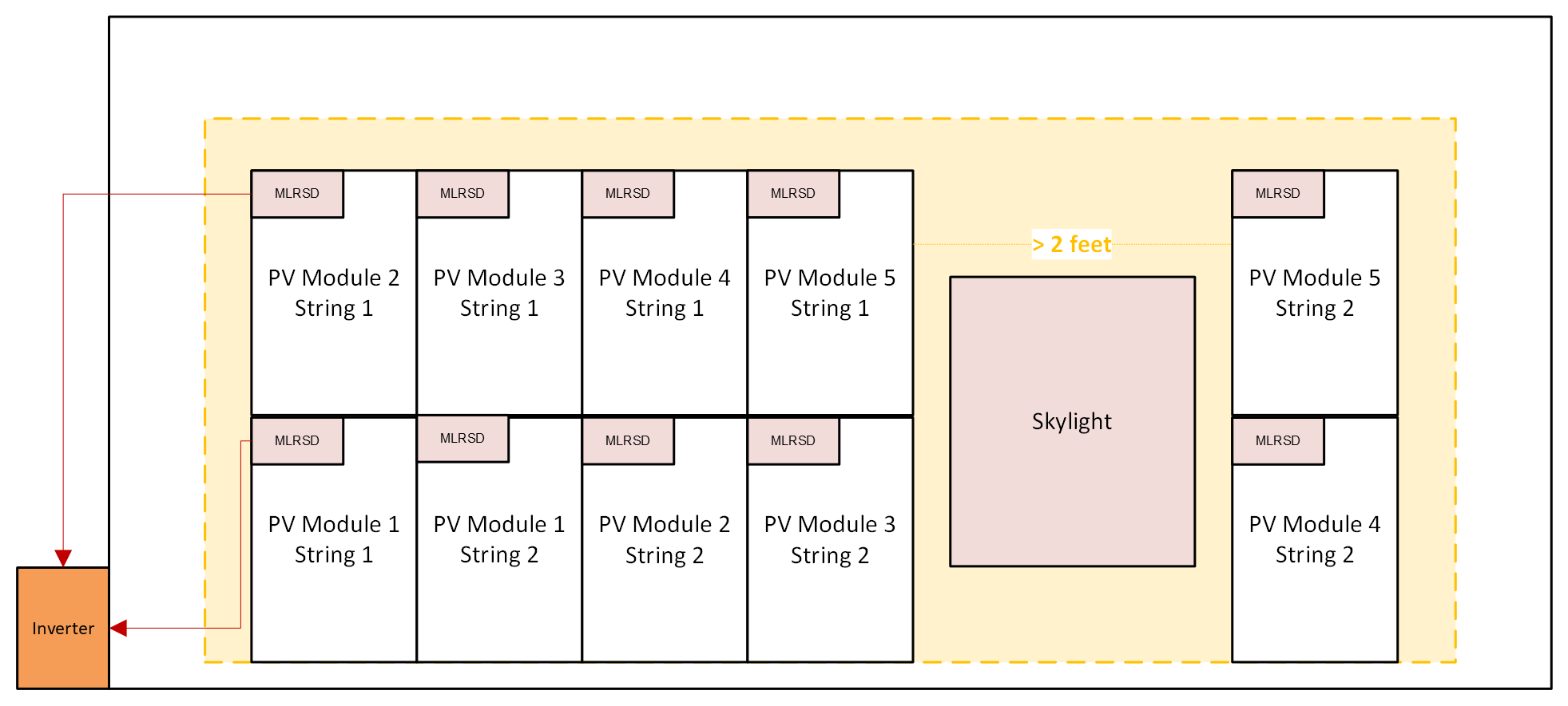
A PV array becomes non-contiguous when there is a physical gap, or separation of more than 2 feet, between different parts of the array. While large commercial arrays consisting of 20 to 40 modules rarely encounter physical boundary issues, residential rooftops frequently require arrays to be split across different roof planes or physically separated to avoid obstacles like vents and dormers.
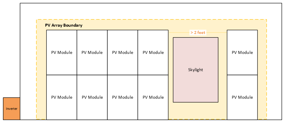
When a PV array is physically separated, determining how to comply with rapid shutdown rules becomes critical. If an array is non-contiguous, installers must utilize one of the following three compliance strategies:
1. Create a Dedicated String (String-Level RSD)
A separated array can be treated as its own independent string with its own dedicated string-level rapid shutdown device. However, to generate power, this separated array must meet the inverter's minimum input startup voltage.
The minimum startup voltage for the inverter is 100V.
Best Practice: We highly recommend designing the string to produce at least 120V (a 20% buffer) to account for voltage drops and varying environmental conditions.
Keep in mind that a small sub-array of only 3 modules is typically insufficient to hit this voltage threshold; 4 or more modules are usually required depending on the specific module voltage.
The smaller string must connected to a separate MPPT from the larger strings as the drawing below shows.
2. Use Module-Level Rapid Shutdown (MLRSD)
If the separated array is too small to meet the 120V recommended startup threshold and extending the racking material is not viable, the system must utilize module-level rapid shutdown (MLRSD) instead of string-level RSD.
Critical Rule: You cannot mix module-level rapid shutdown devices and string-level rapid shutdown devices on the same inverter. If MLRSD is required for a small, non-contiguous sub-array, the entire system connected to that inverter must utilize MLPE and not SLRSD.
5. Approved Equipment
To have a fully UL 3741 compliant system you must select an inverter model with an integrated APS transmitter and TT Solar SLRSD devices, model number JMS-PS1(B). Additionally, you will have to use one of the UL 3741-certified racking systems that has achieved approval with Solis hybrid models.
5.1 Solis S6-EH2P(9.6-16)K-SV-YD-L-US hybrid inverter models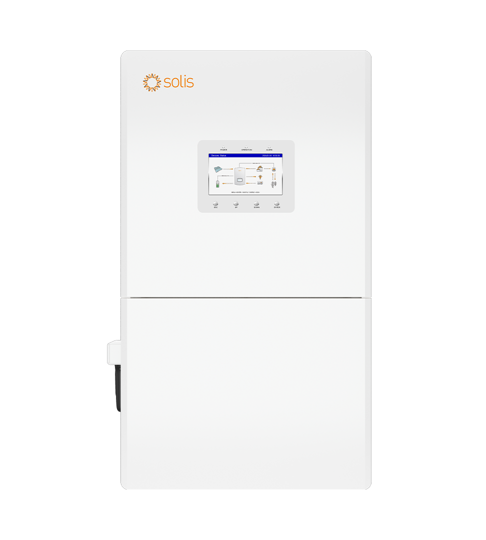 The following S6-EH2P(9.6-16)K-SV-YD-L-US split-phase low-voltage hybrid inverter models (240 VAC) are approved for the UL 3741 pathway with the APsmart Transmitter-PLC integrated. When ordering, add the -APST suffix to specify the factory-integrated transmitter.
Solis model number | Rated output | Ordering SKU with APS transmitter |
S6-EH2P9.6K03-SV-YD-L-US | 9.6 kW | S6-EH2P9.6K03-SV-YD-L-US-APST |
S6-EH2P11.4K03-SV-YD-L-US | 11.4 kW | S6-EH2P11.4K03-SV-YD-L-US-APST |
S6-EH2P12K03-SV-YD-L-US | 12 kW | S6-EH2P12K03-SV-YD-L-US-APST |
S6-EH2P14K03-SV-YD-L-US | 14 kW | S6-EH2P14K03-SV-YD-L-US-APST |
S6-EH2P16K03-SV-YD-L-US | 16 kW | S6-EH2P16K03-SV-YD-L-US-APST |
SKU convention. The full series designation is S6-EH2P(9.6-16)K-SV-YD-L-US. Individual model numbers follow the form S6-EH2P9.6K03-SV-YD-L-US, S6-EH2P11.4K03-SV-YD-L-US, and so on. "S6-EH2P" is used as shorthand for the full series throughout this document.
5.2 APSmart PLC Transmitter (integrated)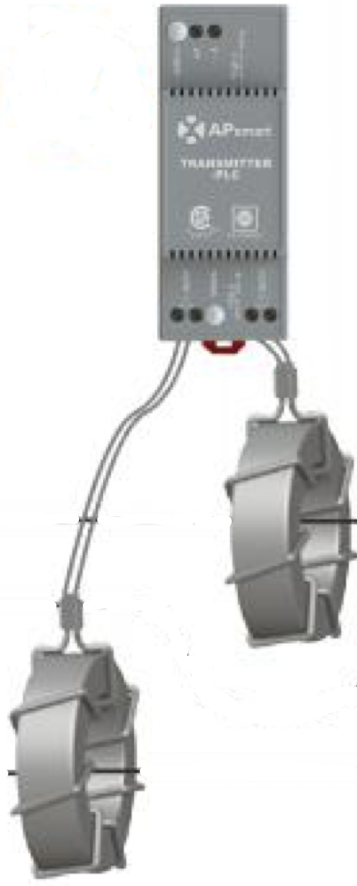
The transmitter integrated into the Solis S6-EH2P when ordered with the -APST suffix is a single-core APsmart Transmitter-PLC variant. It has one PLC core through which up to six PV strings can be routed, and it supports up to 20 A per string. This capacity is well in excess of typical residential PV string currents.
Characteristic | Value |
Configuration | Single-core Transmitter-PLC, factory integrated |
Ordering method | Add -APST suffix to the inverter model number |
Max current per string | Up to 20 A |
Signal type | SunSpec PLC |
External use | Yes, the same transmitter can be installed externally as an alternative to using the integrated transmitter |
Consult APsmart directly, or contact Solis USA sales, for the exact part number of the integrated variant before submitting bills of materials or spare-part orders. RSD equipment cannot be mixed and matched across brands; the APsmart Transmitter-PLC is SunSpec Alliance certified for use with APsmart RSD-S-PLC, RSD-D, RSD-D-15, and RSD-D-20 module-level receivers, and with the TT Solar JMS-PS1(B) SLRSD receiver, only.
5.3 TT Solar JMS-PS1(B) String-Level RSD receiver
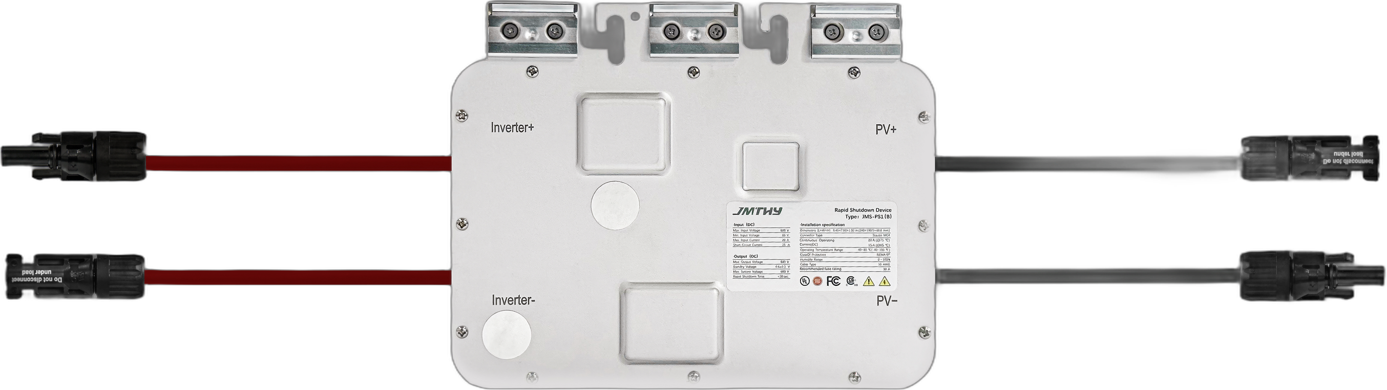
The TT Solar JMS-PS1(B) is a string-level rapid shutdown receiver that uses the SunSpec PLC protocol. It is the SLRSD device Solis lists for use with the S6-EH2P(9.6-16)K-SV-YD-L-US inverter series in the UL 3741 residential pathway.
5.3.1 Essential specifications
The following essential specifications are drawn from the TT Solar JMS-PS1(B) product datasheet.
Parameter | Value |
Max input voltage (DC) | 600 V |
Min input voltage (DC) | 65 V |
Max input current | 20 A |
Short-circuit current | 25 A |
Max output voltage (DC) | 600 V |
5.3.2 Installer note on model naming
The TT Solar SLRSD device is sometimes referred to informally as JMS1-PB. The correct model designation as it appears in Solis and NRTL documentation is JMS-PS1(B). Use the correct form on all bills of materials, submittal drawings, permit packages, and NRTL certification lookups.
5.4 UL 3741-Certified PV Racking Systems
Solis hybrid models are approved to be installed under UL 3741 for the following PV racking systems:
- Ironridge XR Flush Mount
- Ironridge Aire Flush Mount
- Ironridge XR Tilt Mount
- Ironridge Aire Tilt Mount
- Ironridge BX
- Ironridge/Quickmount Clickfit
- Ironridge/Quickmount Rockit or ROKR
- PanelClaw clawFR and clawFRplus
6. Installation Instructions
The steps below combine the PV and rapid shutdown installation procedures from the Solis S6-EH2P(9.6-16)K-SV-YD-L-US user manual (V2.7, 2026-03-05) and the TT Solar JMS-PS1(B) installation manual (V1.3, 2026-06-15). Always follow the manufacturer manuals for the complete procedure, torque specifications, and safety warnings; the summary below is not a substitute for those documents.
6.1 Pre-installation checks
- Verify the PV array is fully disconnected from the inverter before beginning work.
- Use a multimeter to confirm the PV string voltages are 0 V. If rapid shutdown is active, under 30 V DC per string is safe.
- Confirm the polarities of each PV string are correct: positive to positive, negative to negative.
- Confirm the inverter DC switch, battery breaker, AC-Backup breaker, and AC-Grid breaker are all in the OFF position.
- Confirm the PV insulation resistance to ground is higher than 20 kΩ.
- Confirm that the DC voltage of each PV string will not exceed the S6-EH2P maximum input voltage of 550 V on the coldest expected day (calculated using module Voc, temperature coefficient, and worst-case local temperature).
- Confirm the Isc and Imp of each string will not exceed the S6-EH2P maximum input current of 20 A per string (max short-circuit current 25 A per string).
- Verify strings connected to the same MPPT are within ±10 % of each other in DC voltage.
6.2 Installing the JMS-PS1(B) SLRSD receivers
One JMS-PS1(B) is installed per PV string. The device must be installed under the PV modules, never in direct sunlight, with at least 3/8 in of clearance from the module backsheet for ventilation. Maintain a minimum DC cable bending radius of 40 mm.
Option A: Fasten directly to the PV racking
- Use M6 × 20 mounting screws to pre-position the JMS-PS1(B) at the designated mounting location on the PV racking.
- Engage the JMS-PS1(B) onto the mounting bolts with the labeled side facing down. Torque the bolts to the manufacturer's recommended specification.
- Bond the grounding conductor to the metal mounting plate using a serrated lock washer and mounting bolt, then bond the grounding conductor to a code-compliant grounding electrode.
Option B: Fasten to the PV module frame
- Fasten the three metal clips to the metal mounting plate using M4 × 8 flat-head screws.
- Confirm the metal clips are securely fastened.
- Insert the three metal clips into the aluminum frame of the PV module.
- Confirm the JMS-PS1(B) is securely fastened to the module frame.
Wiring the JMS-PS1(B)
- Mate the PV string output connector to the JMS-PS1(B) input connector. Verify polarity before making the connection.
- Wire the JMS-PS1(B) output connector to the corresponding inverter DC input.
- Use 10 AWG PV cable with Staubli MC4 connectors. Do not mix connector brands.
- Install PV wiring inside protective raceways (conduit, wireway, or cable tray) per NEC. No exposed wiring.
- Do not install multiple JMS-PS1(B) devices in series with each other. Do not install multiple JMS-PS1(B) devices in parallel with each other. One device per PV string, up to 600 V per string.
6.3 Connecting PV strings to the S6-EH2P inverter
The S6-EH2P has three MPPTs with two PV string inputs each. After the JMS-PS1(B) devices are installed, connect their outputs to the inverter DC input terminals as follows:
- Strip 1/2 in of sheath from the end of each PV cable.
- Pull up on the orange tab above the target PV terminal to open the terminal gate.
- Insert the end of the PV cable into the open terminal.
- Push the orange tab down to clamp the terminal gate onto the PV cable.
- Give the PV cable a gentle tug to confirm the connection is tight. If the connection feels loose, repeat Steps 1 to 4 and push the cable deeper into the terminal before releasing the lever.
Caution: If DC conductors are accidentally reversed, or if the inverter is not operating correctly, do not turn off the DC switch. Doing so may cause a DC arc that damages the inverter or starts a fire. Instead, measure the DC string current with a DC clamp multimeter, wait for the current to drop below 0.5 A (either by waiting for reduced irradiance or by covering the modules), then open the DC switch and disconnect the strings.
6.4 Verifying rapid shutdown operation
After all JMS-PS1(B) devices are installed and PV strings are connected, perform the following system test before energizing the inverter for the customer:
- Follow the Solis S6-EH2P inverter start-up procedure to bring the inverter online. The integrated APsmart Transmitter-PLC begins sending the SunSpec keep-alive signal down the DC conductors.
- Observe the JMS-PS1(B) indicator light on each device. Refer to the JMS-PS1(B) manual for indicator status details.
- Press the rapid shutdown initiation switch on the right side of the S6-EH2P inverter. This de-energizes the internal PLC transmitter and initiates rapid shutdown of the PV array (and emergency power off of the inverter).
- Observe the JMS-PS1(B) indicator light on each device. The indicator light changes from continuously illuminated green to continuously illuminated red when the JMS-PS1(B) opens.
- Confirm the home-run DC voltage drops below 30 V within 30 seconds of pressing the initiation switch. With rapid shutdown active, expect approximately 4.7 V per JMS-PS1(B) safety voltage on the string side.
- Twist the rapid shutdown initiation switch clockwise to release it. The internal transmitter re-energizes, the keep-alive signal resumes, and the JMS-PS1(B) receivers close, bringing the string voltages back up to full Voc.
6.5 Additional operational notes
With rapid shutdown receivers installed, PV string voltages should be very low when the receivers are open. Depending on the receiver type, expect between 0.6 and 0.7 V DC per module (module-level receivers) or approximately 4.6 V per JMS-PS1(B) (string-level receiver) after rapid shutdown.
If string voltages remain low unexpectedly, confirm the AC breaker is on and the rapid shutdown initiation switch is popped out. Twist the switch clockwise to verify it is not depressed.
The DC switch does not need to be on for the receivers to receive the PLC signal from the internal transmitter. If an external DC switch is installed, confirm it is on, or the receivers will not see the PLC signal.
Inverters ordered without an integrated transmitter do not include an RSD/EPO E-stop switch. In that case an external initiation switch must be installed.
8. Compatible UL 3741 Certified Racking Systems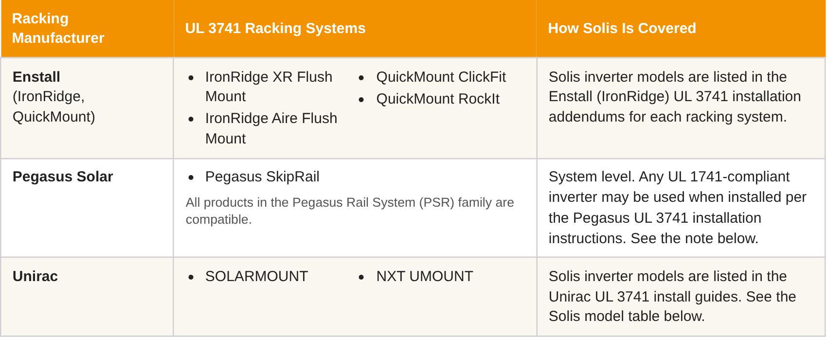
9. Frequently Asked Questions (FAQ)
Q1: Do I still need module-level rapid shutdown if I use UL 3741?
A1: No. That is the point of UL 3741. The listed PV Hazard Control System replaces the 30 V internal-PV-boundary limit that would otherwise force MLRSD. You still need equipment that controls the voltage on the home-run conductors outside the PV boundary and that is what the string-level RSD receiver does.
Q2: Where does the SLRSD device physically go?
A2: Directly under the PV array or at its edge, on the home-run leads that carry DC current back to the inverter. Choose a location that is accessible so the device can be serviced or replaced without lifting modules. One device per PV string. It can be mounted on the PV module frame or on the rail.
Q3: Do I need to run separate control wiring to the SLRSD device?
A. No. The APS transmitter sends the keep-alive rapid shutdown signal down the DC conductors themselves using Power Line Communication (PLC). The same wires that carry PV current also carry the PLC signal.
Q4: Can I use a TT Solar receiver with a Tigo transmitter?
A4: No. RSD equipment cannot be mixed and matched across brands or product lines. The UL 1741 CRD PVRSS certification specifies the exact transmitter-receiver pairing that was tested. The TT Solar JMS-PS1(B) is certified with the APsmart Transmitter-PLC only.
Q5: What voltage can be inside the PV boundary under UL 3741?
A5: It depends on the specific PVHCS certificate. Some listings use 600V. Others use a lower threshold, such as 165V, to be compatible with a wider range of racking systems. The important point is that once UL 3741 is used, 80 V is no longer the ceiling. Outside the PV boundary, the ≤ 30 V within 30 seconds rule still applies, however.
Q6: How is a rapid shutdown event initiated on a Solis S6-EH2P?
A6: Two ways: (1) press the rapid shutdown initiation switch on the inverter, (2) engage an external rapid shutdown initiator wired to the inverter RSD pins. Either of the two stops the PLC keep-alive, and the SLRSD receivers open within 30 seconds.
Q7: What happens during a grid outage if the system is in backup mode?
A7: If the S6-EH2P is providing backup power from the battery and grid AC is lost, the transmitter continues to operate as long as the inverter is running. To fully initiate rapid shutdown in backup mode, press the rapid shutdown initiation switch on the inverter and turn the DC disconnect on the left side of the inverter to OFF. The inverter user manual describes this as engaging the RSD initiation switch to trigger rapid shutdown and emergency power off.
Q8: Who is responsible for obtaining the UL 3741 certification?
A8: The racking manufacturer typically holds the UL 3741 PV Hazard Control System listing. The listing covers a specific combination of modules, racking, mounting hardware, inverter, and SLRSD receivers. Always consult the racking manufacturer's UL 3741 installation addendum before designing or installing the system.
Q9: Is UL 3741 required, or is MLRSD still an option?
A9: MLRSD is still fully permitted under NEC 690.12(B)(2). UL 3741 is just an alternative that many installers prefer because it reduces the number of receivers, simplifies troubleshooting, and can lower equipment cost. Choose the pathway that best fits the project.
Q10: How do I check which racking systems are UL 3741 certified and approved with Solis?
A10: Refer to the current Solis USA and Canada Compatibility List (PE-CP-0005-R00) at solisinverters.com/us or contact Solis USA service at usservice@solisinverters.com. The compatibility list identifies each certified pairing and flags any that are still pending PVRSS or UL 3741 certification.
Was this article helpful?
That’s Great!
Thank you for your feedback
Sorry! We couldn't be helpful
Thank you for your feedback
Feedback sent
We appreciate your effort and will try to fix the article