If the issue persists after the steps below, contact Solis Support at usservice@solisinverters.com or (866) 438-8408, option 2.
Before you start: three checks
- Check that the battery is compatible. Check the battery model against the current Solis compatible battery list: Compatible Batteries & Non-Compatible Batteries. Only batteries on this list can be used in closed-loop communication with the inverter. If the battery is not on the list, this guide does not apply, and closed-loop operation cannot be supported. If you are using open-loop with the 9.6-16 kW low voltage residential hybrid, please skip this step.
- Update the inverter firmware. Update the inverter using the SolisCloud app connected to the inverter over Bluetooth: Upgrading Solis Hybrid Inverter Firmware Locally.
- Check and update the battery BMS firmware. Older batteries often need a BMS firmware update to communicate with the inverter. Check the battery's BMS firmware version with the battery manufacturer and update it if it is out of date. Update both the inverter and the BMS at every commissioning.
The rest of this article assumes that the battery is on the compatible list and that both the inverter and BMS firmware are up to date.
Troubleshooting Inverter-BMS Communication Related Issues
Always start with the inverter alarm
Start troubleshooting from the alarm the inverter is showing. The alarm tells you which type of problem to look for.
- NO-Battery: the inverter measures 0 V on the battery DC terminals. This is a hardware or wiring issue, not a communication issue.
- BatName-FAIL: no battery profile has been selected, the wrong profile is selected for the installed battery, or the BMS DIP switches are set incorrectly.
- Batt_Comm_FAIL: the inverter measures voltage on the battery DC terminals, but communication with the BMS is abnormal.
- UN-Vbatt: the inverter measures the battery voltage as abnormally low.
- OV-Vbatt: the inverter measures the battery voltage as abnormally high.
- Alarm-BMS: communication is working, but the BMS is reporting an internal alarm. Check the BMS using the battery's app.
Not every battery problem produces an alarm. Some problems show up only as unusual behavior caused by poor communication.
BMS communication alarms:
Batt_Comm_FAIL
BatName-FAIL
CAN_Comm_FAIL
BMS_Fault
Step 1: Check whether the inverter is receiving data from the BMS
In SolisCloud, open the inverter and look at the battery BMS parameters (for example, battery SOC, BMS voltage, and the BMS charge and discharge current limits). This tells you which of two very different problems you have.
A. The inverter IS receiving BMS data. The cable is working, and the problem is one of the following:
- The wrong battery profile is selected. Go to Settings → Battery Select. The North American profiles are Lithium Battery LV, PYLON_LV, PYTES and SOLUNA. Most batteries use Lithium Battery LV or PYLON_LV. Do not select a profile with "RS485" in the name.
- There is a CAN protocol mismatch between the inverter and the battery. Think of it like a phone call: the call is connected, but you can only hear bits and pieces of what the other person is saying. Confirm the profile with the battery manufacturer, and check that the BMS DIP switches are set for Solis.
B. The inverter is NOT receiving any BMS data. This is most likely a communication cable or wiring problem. Work through Steps 2 to 5 in order.
Step 2: Check that the CAN port pinouts match
The Solis hybrid uses the standard CAN pinout on its BMS port: Pin 4 = CAN-H (blue) and Pin 5 = CAN-L (blue-white). See Section 5.12.4 of the hybrid manual (page 71): S6-EH2P(9.6-16)K-SV-YD-H-US Manual.
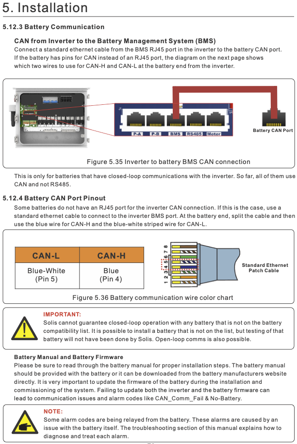
Figure 1. Solis hybrid inverter BMS CAN port and pinout (manual Section 5.12.3 and 5.12.4)
Next, find the CAN port pinout in the battery manual and compare it with the Solis pinout.
Example only, not a rule for all batteries: the Discover battery below has CAN-H on pin 4 and CAN-L on pin 5 of its COM2 port, which matches Solis. For this pairing, a standard straight-through ethernet cable works. In a standard T568B cable, pin 4 is blue and pin 5 is blue-white, which matches the Solis color chart.
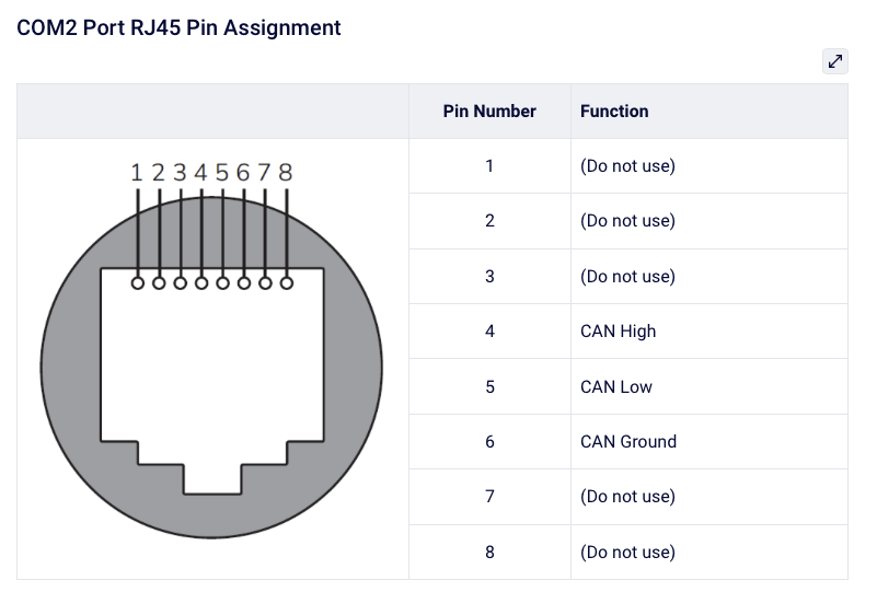
Figure 2. Example: Discover battery COM2 port RJ45 pinout (pin 4 CAN High, pin 5 CAN Low, pin 6 CAN Ground)
Important: Other batteries may use a different CAN port pinout that does not match Solis. Always check the battery manual. If the pinouts do not match, a standard factory cable will not work, because factory cables are wired the same at both ends. Make a custom cable by hand so that CAN-H on the inverter connects to CAN-H on the battery, and CAN-L to CAN-L.
Step 3: Test the cable and photograph both ends
- Test the CAN cable with an ethernet cable tester to confirm it is made correctly. When RJ45 connectors are crimped by hand, the wires can easily get crossed.
- Do not assume a factory-made cable is correct, whether it came from Solis or from the battery manufacturer. Every cable must be tested.
- Get photos of both ends of the CAN communication cable. This is essential for identifying a possible production issue.
Step 4: Check the cable run for noise
Once the cable has been tested and confirmed good, check the installation:
- Distance: how far is the BMS from the inverter? CAN is not designed for long distances. Keep the run as short as possible, and use CAT6 cable for long runs (over 50 ft to be safe).
- Cable type: is it CAT5, CAT5e or CAT6? Is it shielded or unshielded?
- Routing: is the cable run in a conduit with power-carrying conductors? If so, it must be a shielded cable. High-frequency noise from the inverter's switching can interrupt CAN data.
- Grounding: a poor or floating ground can induce noise that looks like a bad cable. Make sure there is a solid, shared equipment grounding conductor between the battery chassis and the inverter chassis.
Step 5: Check the battery-side CAN settings
- Termination: the CAN network needs 120 Ω termination at both ends. The inverter usually has this built in. On the battery side, you may need to install an RJ45 termination plug in the last open communication port, or set a termination DIP switch, depending on the manufacturer.
- BMS DIP switches: many batteries have DIP switches with a specific setting for each inverter brand. If they are not set for Solis, there will be no communication.
- Battery addressing: in parallel battery stacks, set the master battery to address 1 (or 0, depending on the brand). The CAN cable from the inverter must plug into the master battery's CAN (or "Link Port 0") port.
- Restart: do a hard reset. Turn off the AC breaker, the PV switch, then the battery breaker. Wait 5 minutes until the screen is completely dark. Turn on the battery first, then AC, then PV.
Still no communication? Flag it as a quality issue
If the battery is compatible, the firmware is up to date, the pinouts match, the cable has tested good and the installation checks out, flag the case as a quality issue. Email michael.allen@solisinverters.com with:
- Your findings from each step above
- Photos of both ends of the CAN cable
- The inverter serial number, the battery model and the BMS firmware version
Troubleshooting Other Battery Alarms & Issues
NO-Battery alarm
The inverter sees 0 V on the battery DC terminals.
- Measure the voltage at the inverter's battery DC terminals with a multimeter. It must be between 42 V and 58 V.
- Check the breakers: make sure the battery's internal breaker and any external DC disconnects are closed.
- Wake up the BMS: a deeply discharged battery may be in sleep mode. Most batteries have a Start or Reset button that starts the pre-charge circuit.
- Check polarity: make sure BATT+ and BATT− are not swapped.
UN-Vbatt alarm
The battery voltage has dropped below the inverter's operating cutoff (typically 40–42 V) or the BMS's internal protection threshold.
- Measure the voltage at the inverter's DC terminals. Below 40 V, the inverter will not detect the battery and will not start charging.
- Wake up the BMS: press and hold the battery's Start or Reset button to trigger the pre-charge circuit. This should provide enough voltage for the inverter to detect the battery.
- Manual charge: if the BMS is active but the voltage is too low for normal operation, go to System Settings → Storage Mode → Charge/Discharge Schedule and set a charge window to charge the battery from PV or the grid.
- Check the discharge settings: raising the Force Charge, Recover and Over Discharge SOC% settings helps prevent repeat undervoltage events when solar production is low. Recommended: Over Discharge SOC 15–20%, Force Charge SOC 10–15%, and Recover SOC 1–2% above Force Charge.
OV-Vbatt alarm
Overvoltage usually means the inverter is charging a battery that is already full, or the battery has a cell imbalance.
- Check the charge setpoints: in Battery Select → User-Defined (open-loop only), make sure the Charge Limit Voltage is not above the battery manufacturer's maximum (usually 56–58.4 V).
- Resync the communication: in closed-loop mode the BMS sets the charge voltage. If the inverter overshoots it, do a full power cycle (battery, then AC, then PV).
- Check for cell imbalance: if the pack voltage looks normal (for example 54 V) but the alarm continues, one cell may be spiking. Check the battery's app or LED indicators.
- Reduce the charge current: temporarily lower Max Charge Current (for example from 100 A to 50 A) to give the BMS time to balance the cells.
Alarm-BMS alarm
Communication is working, but the battery is reporting an internal hardware or environmental problem.
- Temperature: most BMS faults are temperature related. Keep the battery space between 10 °C and 40 °C (50–104 °F). Lithium batteries often stop charging below freezing.
- LED codes: use the battery manual to decode the LED pattern. It usually points to over-current, a short circuit or a MOSFET failure.
- Clear the fault: turn off the battery's DC breaker and logic switch, wait 60 seconds, then restart.
- Test modules one at a time: with several battery modules in parallel, disconnect them and test each one with the inverter to find a faulty module.
Was this article helpful?
That’s Great!
Thank you for your feedback
Sorry! We couldn't be helpful
Thank you for your feedback
Feedback sent
We appreciate your effort and will try to fix the article