This is only a guide for commissioning Renon Xcellent Plus battery with Solis 16K LV Hybrid. For more detailed instructions please see the Installation & Local Commissioning Guide


Inverter-Side CAN Cable Connection
The pinouts match on both battery and inverter ends. Connect one end of the cable to the “BMS” RJ45 port of the inverter as shown below. You can use a CAT6 shielded cable to connect the two ports together. Be sure to use an ethernet cable tester to ensure both connectors were made correctly and the cable works.
Pin 4 (blue) is CAN-H (CAN High)
Pin 5 (blue-white) is CAN-L (CAN Low)

Battery-Side CAN Cable Connection
Connect the other end of the CAN cable to the “Inverter COM” RJ45 port on the battery. Alternatively, you can use the terminal block shown as “Option 2” in the drawing below.
IMPORTANT NOTE
The battery and inverter communication port pinouts do not match. You must not use a standard ethernet cable, it will not work. A custom cable will need to be made so that the system will function normally.


Option 1: Battery “Inverter COM” (CAN) RJ45 Port Pinout
The pinouts are different so please be extra cautious when making the CAN cable between the inverter and the battery. It is safer to use Option 2 since you can more easily determine if the CAN_H and CAN_L is correct on the battery-end.
CAN_H = Pin 4 on the inverter end = Pin 7 on the battery end
CAN_L = Pin 5 on the inverter end = Pin 8 on the battery end

Option 2: Battery “Inverter COM” (CAN) Terminal Block Port
If you are using this option be sure to connect pin 4 (CAN-H) blue wire on the inverter end to pin 5 on the battery terminal block. Pin 5 (CAN-L) blue-white wire on the inverter end will go to pin 4 on the battery terminal block.


Initial DIP Switch Setup
Before powering on the battery, you must configure the physical switches for commissioning.
- Set the Address & Function Switches: Set the Address dial code (Addr. SET) to Code 1. Set the Function dial code (Function SET) to Code 4.
- Set the Inverter Switch for Commissioning: Set the Inverter dial code (INV SET) to Code 63. To do this, flip all switches (1 through 6) to the ON position. This specifically places the battery into Wi-Fi configuration mode.

Powering the System On
Battery
Turn on the battery breaker (Power button): If there are any other disconnect switches installed between the battery and the inverter, switch these to the ON position before powering on the battery. Also be sure the battery breaker inside the Solis inverter wire box is turned ON (up).

Short press the power button under the LED lights to turn the battery on. This is the “Button” shown below.

Inverter
- Turn on AC power from the grid to the inverter. If this is an off-grid setup, then you do not have to do this. If you have PV, be sure any external PV disconnect switches are closed and the array is ready to be energized.
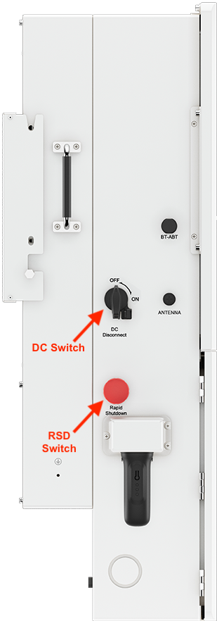
- Turn on the DC disconnect switch located on the side of the inverter.
- Give the red RSD switch a clockwise turn to ensure it is open and not closed. Pushed in means closed (RSD engaged). The button also serves as a soft shutdown emergency power off (EPO) switch. It is a dual purpose switch.
Renon App and Settings Configuration
With the battery powered on and the INV SET switch at Code 63, you must now use the Renon Smart app to commission the system. This process involves connecting to the battery via Bluetooth, entering your private Wi-Fi network credentials, creating a power station profile, and binding your specific device's serial number.
Because this requires navigating multiple menus, verifying codes, and setting up cloud monitoring, please refer directly to the full manual (Section 3.7) for the complete step-by-step screenshots.
Renon Xcellent Plus manual: https://www.renonpower.com/uploadfile/2024/1009/20241009095219100.pdf
Renon Smart App (Google): https://play.google.com/store/apps/details?id=com.renon.rcloud
Renon Smart App (Apple): https://apps.apple.com/us/app/renon-smart/id6526464484
Battery DIP Switch Setting Specific to Solis
Once the Wi-Fi configuration is completely finished in the app, you must change the Inverter dial code (INV SET) from Code 63 to the specific code shown below for Solis. Switch 3 in ON (up) position and the rest of the switches in the OFF (down) position.

Download the SolisCloud App:
- Now you will need to configure the inverter settings using the SolisCloud app. This can alternatively be done through the LCD. In the App Store/Play Store search for “SolisCloud” and then download the app that has the same icon as this one:

- Register a new Organization account if you are installer and have not yet set up an account yet.
- Log in to SolisCloud
SolisCloud App: Settings configuration
- Tap Service > Local Debugging > Connect with Bluetooth.
- Create a new password for logging in to the inverter
- Configure the Quick Settings. For the battery, select “Lithium Battery LV"
- Once you reach the main overview screen tap “Settings” in the bottom right corner
- Scroll to the bottom and then tap “Device Upgrade”
- Upgrade the firmware on all paralleled Solis inverter-chargers.
- In the bottom menu bar, select Setting > Device Upgrade.
- Upgrade the HMI and DSP.
Note 1: Upgrading inverter firmware is mandatory.
Note 2: All Solis inverters must be use the same firmware version to operate normally. If you are connecting multiple inverters in parallel be sure they are on the same version.
For a guide on how to upgrade inverter firmware please see this article:
Upgrading Hybrid Inverter Firmware Locally
- After upgrading the firmware, in the phone app tap Battery Setting
- In the Battery Setting page, tap "Battery1Setting"
- Make sure the Battery Model is set to “Lithium Battery LV” if it is not then you will need to first tap "Battery Model" then tap “Lithium Battery LV” and then tap “Save” in the top right corner of the page.


Battery Settings & Energy Storage Mode Settings
Please see this guide for detailed explanations of each and every battery-related setting as well as energy storage and export power settings: Battery, Energy Storage, & Export Power Settings Explained
- Set other inverter battery-related settings as required.For instructions on configuring inverter settings, refer to the full Solis manual or the article linked above.
- After all the settings have been configured, check the overview page of the system.
- Follow all manufacturer instructions to power up the inverter DC switch, and turn ON the batteries and other peripheral equipment.
- Use the overview to confirm the battery SOC, battery communications, grid, and load.
- Review and resolve any generated alarms.
- At this point, if the system is grid-connected, AC grid power is turned on.
- Exit the app once the system is running and all checks are complete.
Depending on your system and particular use case, there may be other settings that require configuration. Refer to the inverter manual for information on these settings.
Was this article helpful?
That’s Great!
Thank you for your feedback
Sorry! We couldn't be helpful
Thank you for your feedback
Feedback sent
We appreciate your effort and will try to fix the article