Note: This article is a simplified version of the full inverter user manual Section 4: Operating Modes & Use Cases. Please see the full user manual Section 4 for all of the details on operating modes and inverter behavior (logic).
The Solis hybrid inverter supports a wide range of use cases with varying degrees of complexity. This
section goes over common applications that the inverter can fit into. Each application includes a system
layout showing what is connected to the inverter and what is not in that specific use‑case. Logic tables
are also included to show how the system behaves in each mode. The purpose of this section is to show
the inverter’s abilities and limitations. It will not explain every possible application since the potential
combinations are numerous. This section starts with the simplest use cases and then gradually gets into
increasingly complex applications as more equipment is added.
- 4.1 PV-Only
- 4.1.1 Grid-Tied PV String Inverter without Export Power Control
- 4.1.2 Grid-Tied PV String Inverter with Export Power Control
- 4.2 PV + Grid + Battery
- 4.2.1 Grid-Tied PV + Battery without an Energy Meter/CTs (Time-of-Use mode)
- 4.2.2 Grid-Tied PV + Battery with an Energy Meter/CTs (Self-Use/Selling First Modes)
- 4.3 PV + Grid + Battery + Backup
- 4.3.1 Grid-Tied Systems Doing Energy Arbitrage with Backup for Emergencies
- 4.4 PV + Grid + Battery + Backup + Smart Port
- 4.4.1 Grid-Tied Systems with a Generator on the Smart Port
- 4.4.2 Grid-Tied Systems with AC-Coupled PV on the Smart Port (Grid-Following)
- 4.4.3 Grid-Tied Systems with AC-Coupled PV on the Smart Port (Grid-Forming)
- 4.4.5 Grid-Tied Systems with a Sheddable Load on the Smart Port
- 4.5 Off-Grid
- 4.5.1 Grid-Forming Mode with PV Only
- 4.5.2 Off-Grid with PV & Battery
- 4.5.3 Off-Grid with PV, Battery, & Generator on the Smart Port
- 4.5.4 Off-Grid with PV, Battery, & a Generator on the Grid Port
- 4.6 Additional Use Cases
- 4.6.1 AC-Coupling Solis as a Battery Inverter (Battery + Grid + ACPV)
- 4.6.2 Grid-Tied with a Generator & an External Auto Transfer Switch (ATS)
- 4.7 Paralleling Multiple Inverters
- 4.7.1 Paralleling Only the Grid Ports of the Inverters (No Backup Ever)
- 4.7.2 Paralleling the Backup Ports & the Grid Ports of the Inverters
- 4.8 Using an External ATS to Protect the Loads
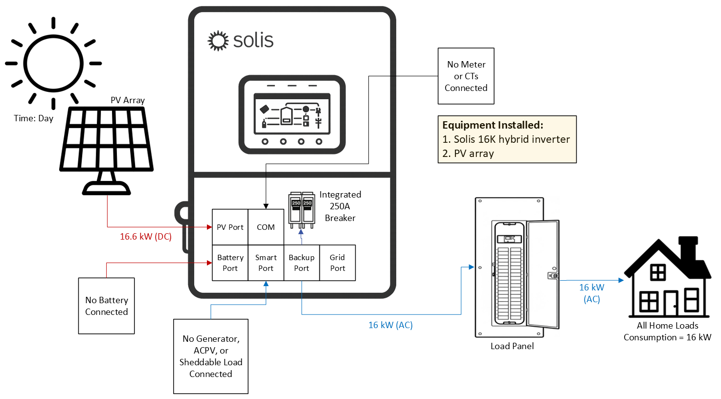
4.1 PV-Only
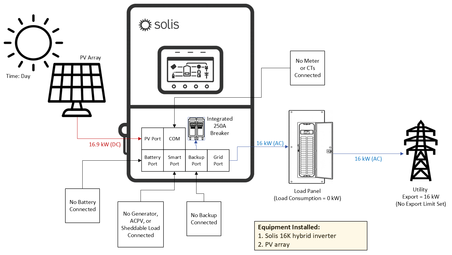
4.1.1 Grid‑Tied PV String Inverter without Export Power Control
This inverter can be used as a PV‑only grid‑tied string inverter. Only the PV and grid ports would be
utilized. The logic is very simple. When the grid is present, the inverter produces as much power from PV
as it can. It does not monitor or control power exported to the grid. If the grid fails, the inverter shuts down
and stops generating power. The inverter is capable of providing backup power with only PV. However,
this section will not discuss backup. When the inverter is used in this fashion, there is no limit from Solis
with respect to how many inverters can be connected in parallel within the same system. The inverter can
be installed like this and a battery can be added later on, making this like a battery‑ready inverter.
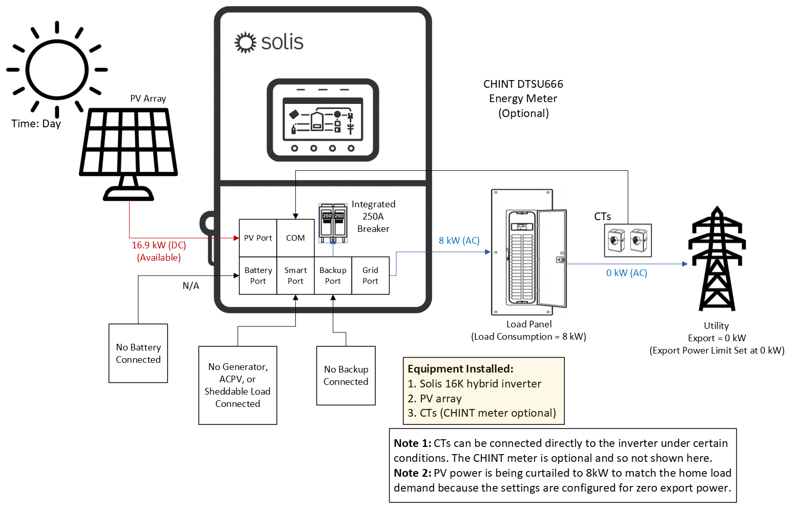
4.1.2 Grid‑Tied PV String Inverter with Export Power Control
The inverter can monitor and regulate export power, defined as excess generation remaining after home
load demand is met and available to be sent to the utility. Unlike the previous application, this function
requires installation of the included CTs or an external energy meter so the inverter can measure power
exchange between the home and the utility. Using this data, the inverter can control export power
(including limiting export to 0 kW) and report export, import, and home load consumption. Installation of
the meter and/or CTs is optional unless the owner wishes to monitor consumption or import/export power.
The external meter and CTs are not equivalent to a revenue‑grade meter (RGM), which measures only
inverter AC output. Each Solis hybrid inverter includes split‑core CTs and an external CHINT energy
meter. The CTs may connect directly to the inverter without the meter only if both of the following
conditions are met꞉ (1) the inverter is installed within 19.68 ft (6 m) of the utility point of common coupling
and (2) the system contains a single inverter. If the distance exceeds 19.68 ft or multiple inverters are
installed, the CHINT meter is required. In this case, the CTs connect to the meter, and the meter
communicates with the inverter via RS485. During commissioning, CT/meter configuration and export‑
power settings must be completed.
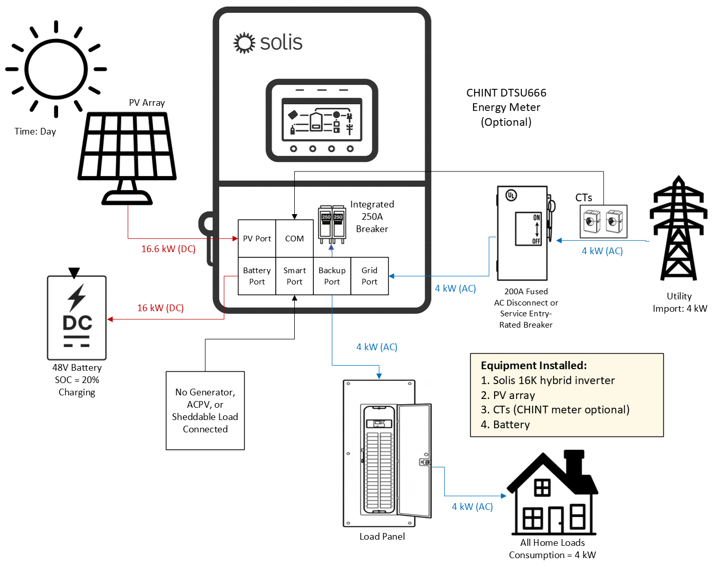
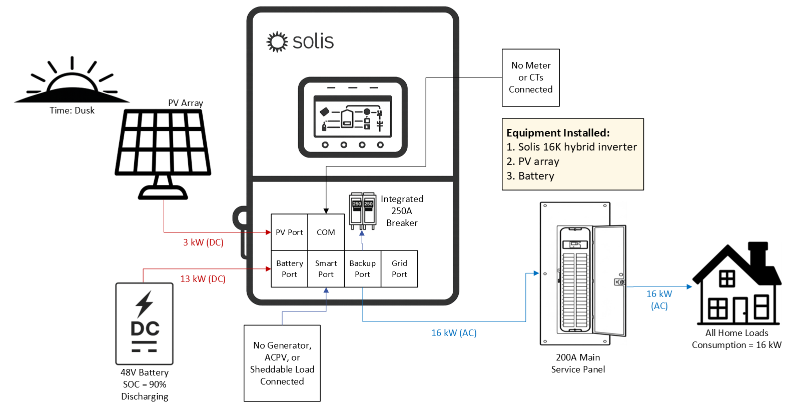
4.2 PV + Grid + Battery
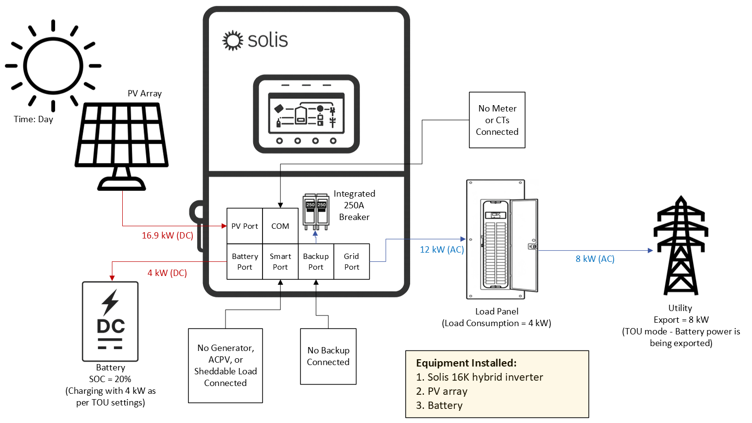
4.2.1 Grid‑Tied PV + Battery without an Energy Meter/CTs (Time‑of‑Use mode)
The inverter has two sets of ports (+) and (‑) for batteries to connect to it. Installation of a battery is not
required, the inverter can operate with PV only as shown in the previous section 4.1. The addition of a
battery allows the inverter to store excess PV power for use when the home load demand exceeds the
available PV power. This is what we call “default self‑use mode”. However, without the external meter &
CTs only time‑of‑use can be used. Time of use is set up by configuring charge and discharge time
windows along with maximum charge and discharge amperage values. The inverter will charge and
discharge the battery based on the configuration of these settings. This can be thought of as a force‑
‑charge mode where the inverter manually charges and discharges the battery. To have the system
automatically charge and discharge based on available PV power, load demand, and export power
settings the external CHINT meter/CTs must be installed.
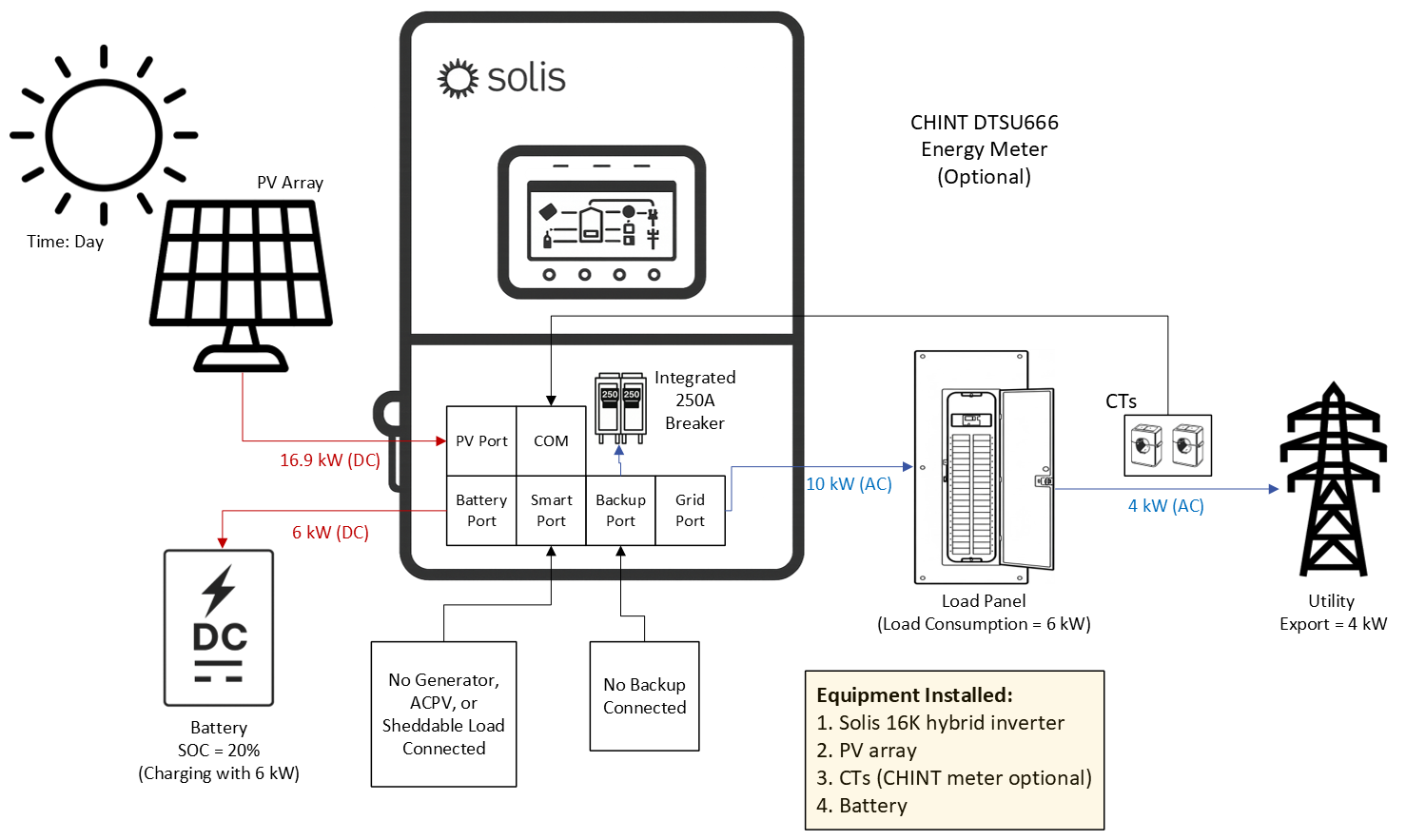
4.2.2 Grid‑Tied PV + Battery with an Energy Meter/CTs (Self‑Use/Selling First Modes)
When the inverter is installed with both a battery and a CHINT meter/CTs it is able to automatically
charge the battery with excess PV power, which is power left over after the home load demand has been
met. This is what we call self‑use mode. The included external meter/CTs must be installed in this case.
If the battery is charged or the charge limit has been reached, any remaining power at that point can be
exported to the utility if the system has been configured to allow that. If the system is configured for zero
export, then the inverter will curtail the AC output power from the PV to equal the load demand such that
there is no power fed back to the utility. The other mode available is selling first mode, which sets export
power as the second priority after load demand with battery charging as third priority.
For the inverter to automatically execute energy arbitrage (self‑use) the meter/CTs must be installed.
Otherwise, only time‑of‑use mode can be utilized. This is because the meter/CTs allow the inverter to
make necessary calculations to determine if power should be dispatched or not to cover load demand.
4.3 PV + Grid + Battery + Backup
4.3.1 Grid‑Tied Systems Doing Energy Arbitrage with Backup for Emergencies
The S6 hybrid is capable of providing AC power to home loads using PV and battery power in the
event of a grid failure. This is known as backup power. The amount of backup power that each S6
hybrid model can provide is equal to the amount of on‑grid power that it can provide. For example,
the 16K model can provide up to 16kW of continuous backup power even when the grid is absent.
The Solis hybrid inverter is capable of alternating between grid forming and grid following modes. It is
able to perform grid forming on the backup port, it cannot grid form on the grid port. Therefore, the terms
“grid‑forming”, “backup”, and “off‑grid” are all used synonymously throughout this manual. When the
inverter senses the grid is no longer present, it opens the relays connecting itself to the grid effectively
shutting off the grid port. It then switches to grid forming mode in under 4 milliseconds and generates AC
power using PV first and then battery if there is no PV or not enough PV to support the loads connected to
the backup side. The inverter continues to operate in this way constantly checking to see if the grid has
returned. Once the grid is present again, the inverter switches back to grid following mode.
4.4 PV + Grid + Battery + Backup + Smart Port
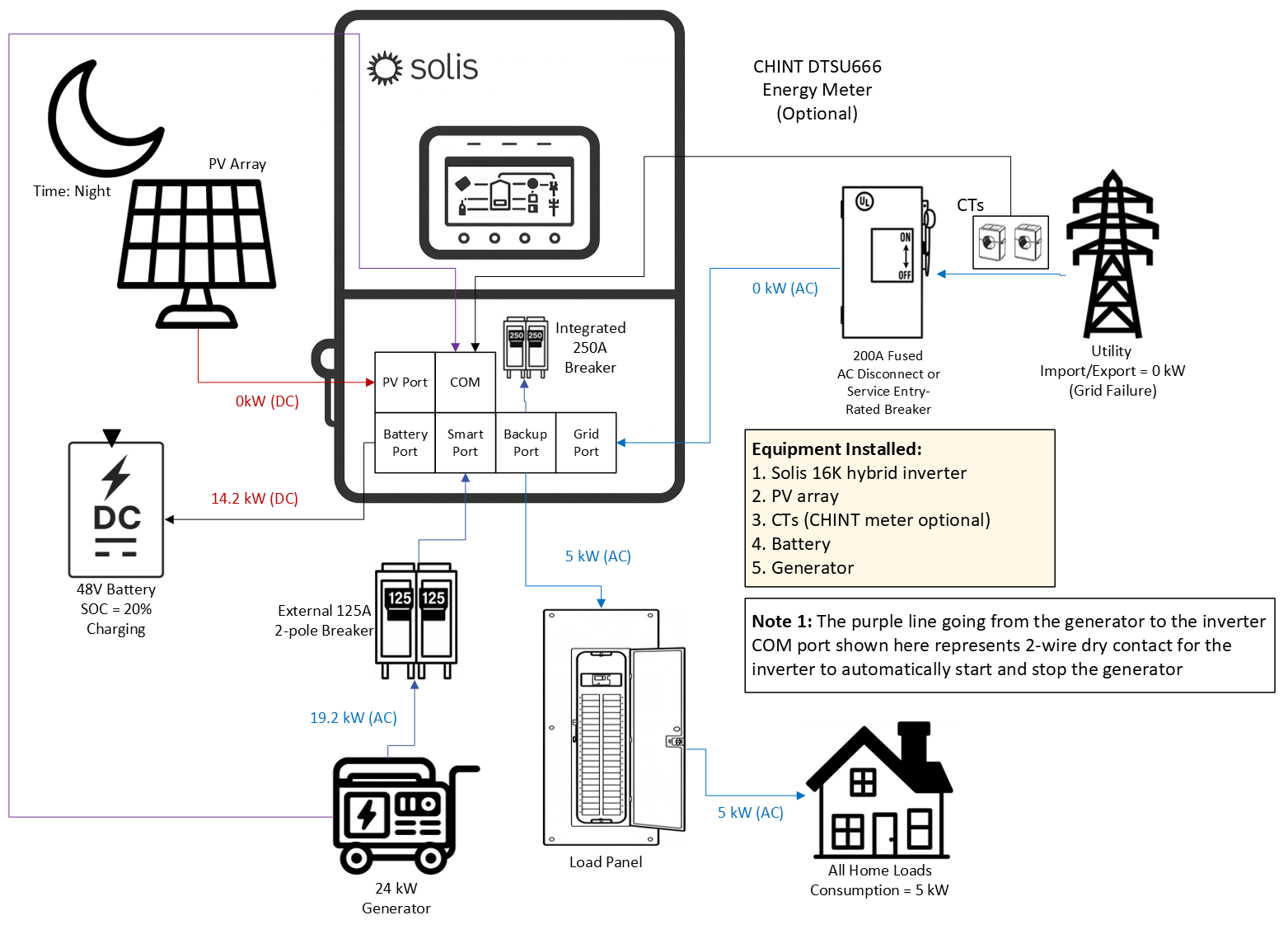
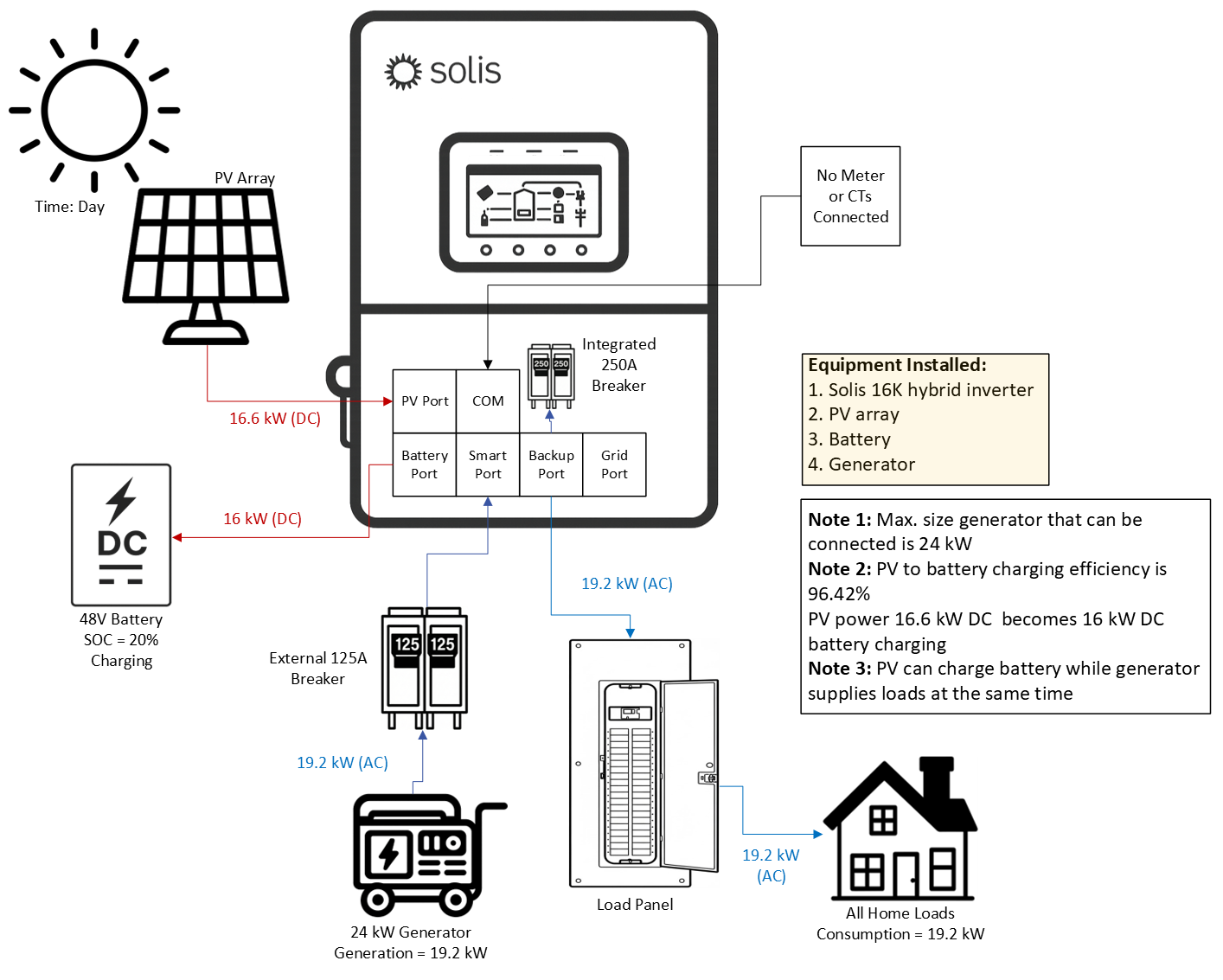
4.4.1 Grid‑Tied Systems with a Generator on the Smart Port
A generator can be connected to the Smart Port of the inverter. The maximum size the generator can be
is 24 kW. The Smart Port is rated for 125A maximium. Considering NEC, 24 kW is the largest generator
that can be connected through a 125A breaker. If a larger generator is to be connected, it can only be
connected on the grid‑side of the inverter. When in backup or off‑grid mode, the inverter will
automatically start/stop the generator based on the battery state‑of‑charge (SOC) percentage.
The generator must support two‑wire dry contact. A two‑wire cable must be run between the inverter and
the generator for dry contact. This is how the inverter is able to start and stop the generator automatically
based on the SOC% of the battery. When the generator is on, the inverter goes back to grid‑following
and sychronizes with the generator. Please do not connect a generator to the Backup port of the inverter.
Generators can only be connected to the Smart Port or to the Grid port (or grid‑side in general).
Dry Contact port is rated for 12-24V/50mA
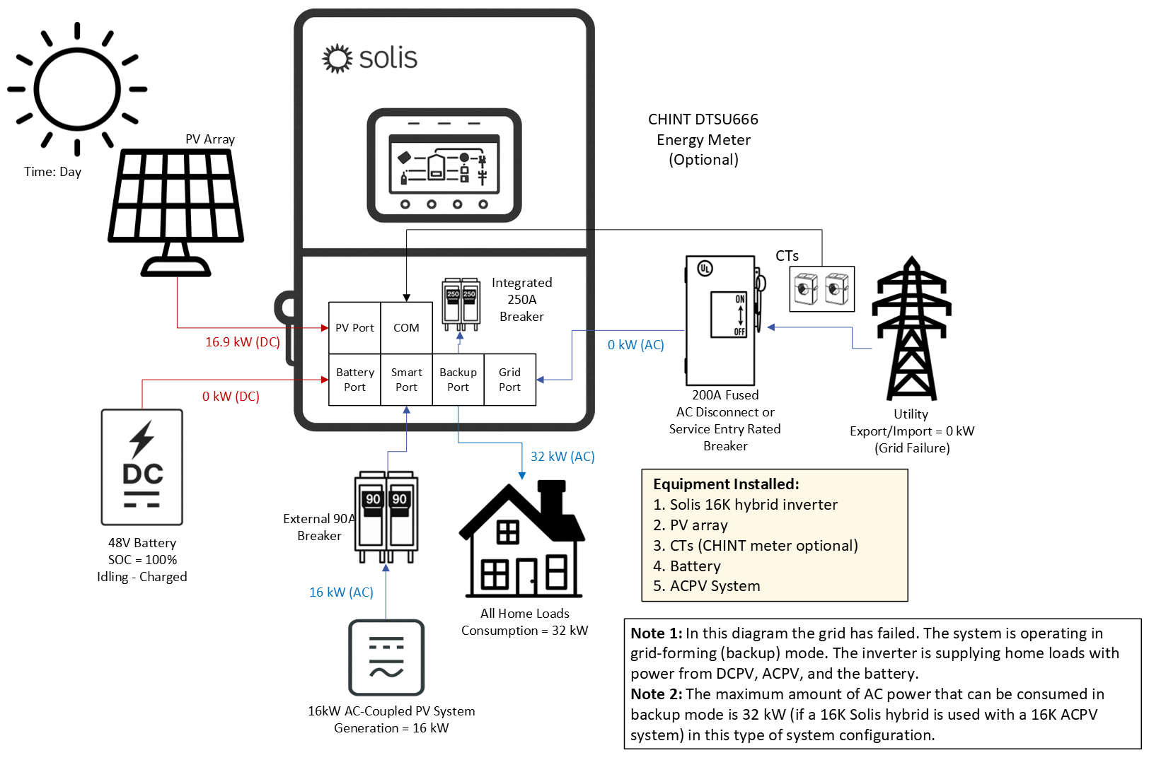
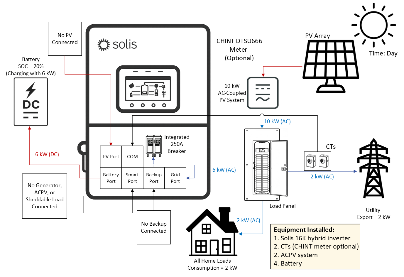
4.4.2 Grid‑Tied Systems with AC‑Coupled PV on the Smart Port (Grid‑Following)
An existing or new AC‑coupled PV (ACPV) system can be connected to the Smart Port of the inverter.
Doing this allows the ACPV system to continue generating power even when the grid has failed or it is an
off‑grid system. The maximum size ACPV system that can be connected is equal to the nameplate rating
of the Solis hybrid. For example, if the Solis hybrid is a 16kW unit, then a 16kW ACPV system can be
connected to the Smart Port. If the system is larger, it must be connected to the grid side of the inverter
and will not be supported in backup/off‑grid mode. The diagram below shows that the maximum amount
of power that can go to loads or to the grid is equal to twice the inverter nameplate rating. In the case
shown below it would be 16kW from the Solis inverter and 16kW from the ACPV system totalling 32kW.
The reason the ACPV system must be the same size or smaller than the Solis hybrid is because the
Solis hybrid must be able to control the ACPV system in grid‑forming mode by shifting the frequency.
It cannot do that if the ACPV system is larger.
4.4.3 Grid‑Tied Systems with AC‑Coupled PV on the Smart Port (Grid‑Forming)
When the grid is absent the Solis hybrid switches to grid‑forming mode. This could either be on‑grid
backup mode or fully off‑grid mode. The inverter will supply the home loads connected to the Backup port
with power from the PV connected directly to the inverter (DCPV) and the ACPV system connected to the
Smart Port. The inverter will also use ACPV power and DCPV power to charge the battery. If the battery
is fully charged and the available PV power exceeds the load demand, the inverter will first curtail the
DCPV power. If the DCPV power has been curtailed to 0kW and the ACPV power exceeds the load
demand, then the inverter will use frequency‑watt shifting in accordance with IEEE 1547 to curtail the
ACPV power. There is no direct communication between the Solis hybrid and the ACPV system.
There is no advantage to connecting the ACPV system to the Smart Port if the system is only ever going
to be on‑grid (no backup at any time). If backup is not being used, it is likely easier and simpler to just
connect the Solis inverter system in parallel to the existing PV system.
The ACPV system connected to the Smart Port of the inverter must either be the same size as the Solis
hybrid or smaller than it. It cannot be larger or else the Solis hybrid will not be able to control the ACPV
system using frequency‑shifting when in grid‑forming (backup/off‑grid) mode.
'
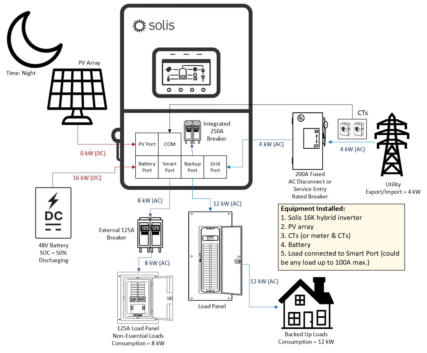
4.4.5 Grid‑Tied Systems with a Sheddable Load on the Smart Port
The last thing that can be connected to the Smart Port of the inverter is a large load, such as an AC EV
charger, an air conditioner, pool pump, or heater. The benefit of doing this is that when in grid‑forming
mode (backup/off‑grid) the battery power can be more efficiently maintained to support priority loads.
During commissioning, you will set an on and off SOC% that dictates when the Smart Port will have power
and not so that the battery does not get drained by supporting that large load indefinitely. The large load
connected to the Smart Port can effectively be shed to save the battery power for more important loads.
The diagram below demonstrates how in grid‑forming mode the Smart Port will be turned off when the
battery reaches 50% SOC at night when there is no PV power available. It is also possible to install a
125A load panel on the Smart Port that houses breakers for non‑essential loads.
Limitations of Using the Smart Port for Load Control꞉
1.The largest load that can be connected to the Smart Port is a load that draws 24 kW
of power or 100A maximum. The largest breaker that should be used is125A per NEC.
2. The load connected to the Smart Port will be supported so long as there is enough
battery power stored to support it. Please be mindful when selecting a load to connect to
the Smart Port that it should be a load that can be lived without when the grid is down.
3. DO NOT install a bi‑directional EV charger on the Smart Port. This is not supported.
4.5 Off‑Grid
Off‑grid systems do not have grid connected at any time. This is not to be confused with grid‑tied systems
that lose grid power from time to time. This section is for systems that never have grid power and operate
entirely with PV, batteries, loads, and a generator.
4.5.1 Grid‑Forming Mode with PV Only
It is possible for the inverter to operate in grid‑forming mode with PV only. This applies to both off‑grid
and on‑grid systems using backup. The inverter will supply AC power to the loads on the backup port
using available PV power. However, it is a delicate balance because if the load consumption exceeds
the available PV power, the inverter will shut off temporarily before turning back on. This type of system
configuration is only supported by one inverter. It is not possible to install multiple inverters like this.
4.5.2 Off‑Grid with PV & Battery
There is a dedicated mode specifically for off‑grid remote systems that are not electrically connected
to the grid at all, such as a cabin in the woods. This mode is not to be confused with backup, which
occurs only for grid‑tied systems. The logic for Off‑Grid mode is the same as Self‑Use mode.
The inverter will use generator power to supply the loads and recharge the battery. For single inverter
systems, it is recommended to have a battery connected to the inverter. For parallel systems (≥ 2
inverters), the inverters must have batteries connected in order to provide power in an off‑grid system.
With PV and batteries, the inverter will supply power to the loads using PV first. Any excess power will
go to charge the batteries. If there is insufficient PV power relative to the load demand, the inverter will
discharge the battery to meet the deficit left after all PV power is utilized. Should the battery be fully
charged and there is more PV power available than load demand, then theinverter will curtail the PV
power to match the load demand.
The external meter does not need to be installed for off‑grid systems.
4.5.3 Off‑Grid with PV, Battery, & Generator on the Smart Port
As discussed in previous sections, a generator can be connected to the Smart Port of the inverter.
The inverter will automatically connect/disconnect the generator as needed in grid‑forming mode using
2‑wire dry contact. When the generator is turned on, the inverter switches to grid‑following mode and
synchronizes with the generator. Power from the generator is used to recharge the battery and support
the home loads. If it is daytime and there is PV power but not enough to support the loads and the
battery drains to the set generator start SOC% then the PV will generate power at the same time as the
generator. PV power will be curtailed if the load demandsuddenly drops or the PV power suddenly
increases due to a rapid increase in irradiance. This is so the generator is not backfed by the PV. The
maximum size generator that can be connected to the Smart Port is 24 kW. If a larger generator is
required, it must be connected on the grid side as shown in the next section.
The external meter does not need to be installed for off‑grid systems. However, if a generator is to be
installed on the grid side, then the meter + CTs should be installed for full monitoring of the generator.
4.5.4 Off‑Grid with PV, Battery, & a Generator on the Grid Port
A generator can also be connected to the grid‑side of the inverter instead of directly to the smart port.
In fact, if the generator is larger than 30 kW it must be done this way. The generator must support dry
contact for the inverter to be able to automatically start/stop the generator based on battery SOC%.
Alternatively, or if the generator does not support dry contact, the generator can be manually started
and stopped. In this manual mode, the inverter will still synchronize to the generator and use the power
from the generator to charge the battery and support loads connected to the backup port. The main
disadvantage of this type of system configuration is additional equipment will be required to connect
the generator since it is not connecting directly to the inverter.
4.6 Additional Use Cases
4.6.1 AC‑Coupling Solis as a Battery Inverter (Battery + Grid + ACPV)
The Solis hybrid inverter can be AC‑coupled to an existing PV system. This configuration involves
installing the Solis inverter with a battery in parallel to an existing PV system. The existing PV system
could be a microinverter system or another type of string‑inverter. Regardless, the Solis inverter will
charge the battery with AC power from the existing PV system and can then be programmed to discharge
that power during certain times for energy arbitrage. This is the most basic setup as there is no additional
PV being installed and connected to the Solis hybrid. Also, the energy meter/CTs are not required.
In this example, the battery can only charge and discharge with time‑of‑use (TOU) settings configured.
If your goal is to have the inverter automatically charge/discharge the battery to minimize grid import
power, the external CHINT DTSU energy meter and CTs will need to be installed so the inverter can tell
when to charge/discharge and with how much power.
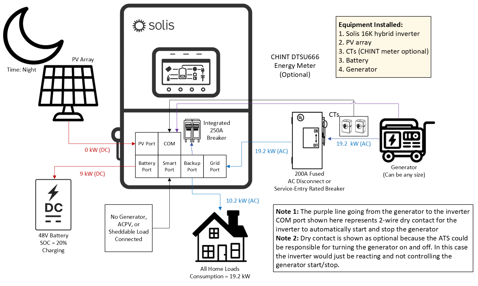
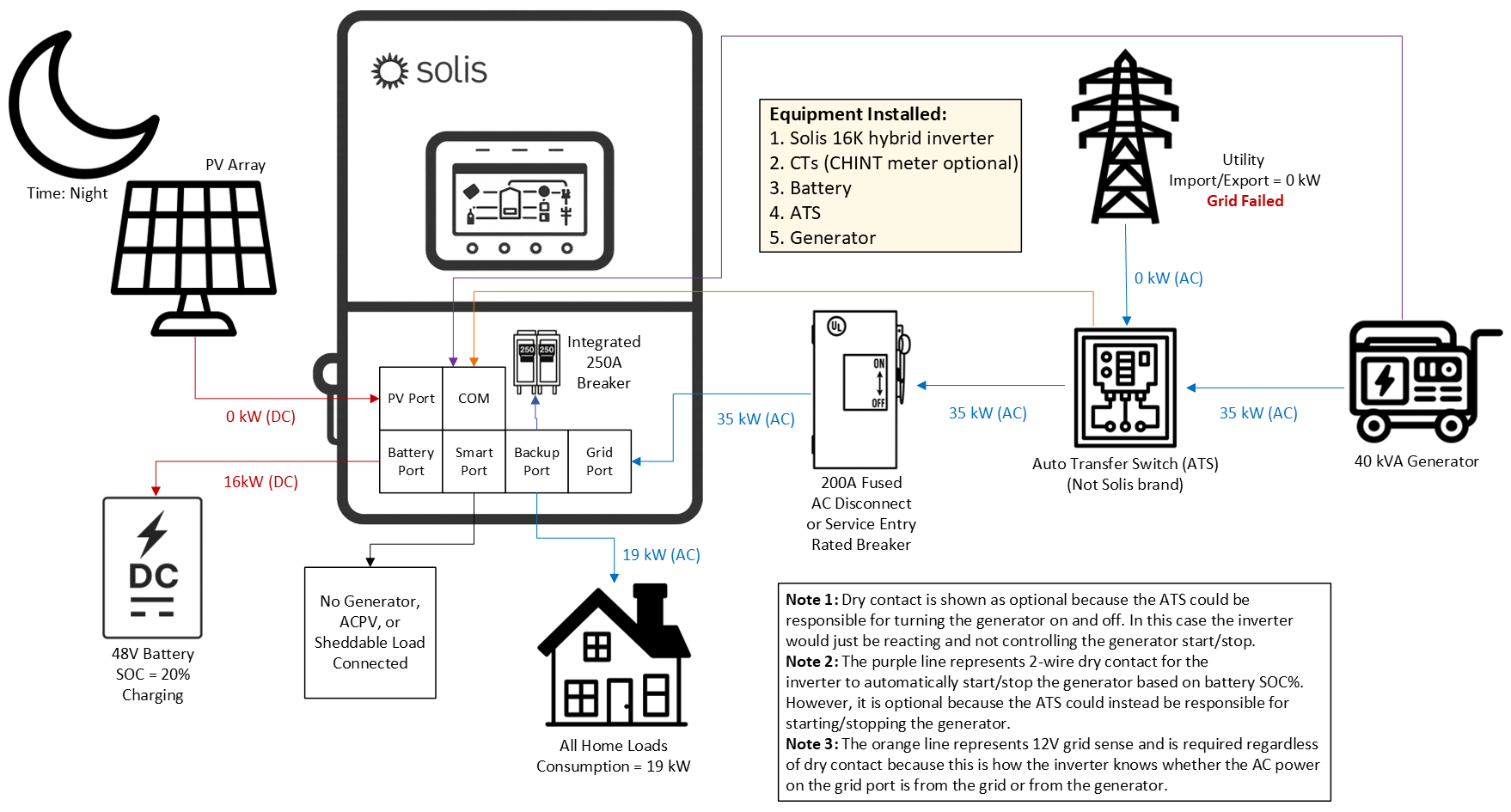
4.6.2 Grid‑Tied with a Generator & an External Auto Transfer Switch (ATS)
In some cases, an existing generator and auto transfer switch (ATS) are already installed. It may be
a significant amount of work to relocate the generator to the Smart Port. The diagram below shows how
to integrate the Solis system with an existing generator/ATS combo. A two‑wire dry contact connection
between the inverter and the generator is optional. If the goal is for the ATS to automatically turn on the
generator, then dry contact is not required. However, if the goal is to have the Solis inverter control the
start/stop of the generator based on the battery SOC%, then dry contact is required. Regardless of
whether or not dry contact is used, a 12V “grid sense” set of two wires must be connected from the ATS
to the inverter. If the ATS does not support 12V grid sense, then a 120VAC to 12VDC power converter
must be installed on the grid side of the ATS and then connected to the inverter. The purpose of the 12V
grid sense is for the inverter to know if the 240V power on the Grid Port is from the actual grid or from the
generator. Without this 12V sense, the inverter will assume the power is always from the generator.
The logic table above assumes that the ATS is controlling the start/stop of the generator not the inverter.
Dry contact is not being used in this case, only 12V grid sense so the inverter can distinguish grid from
generator power.
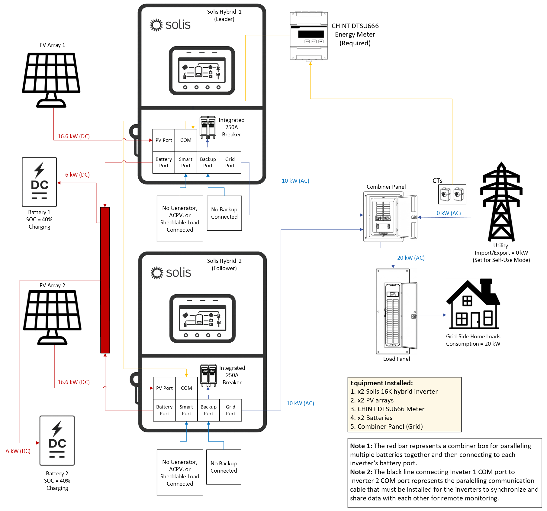
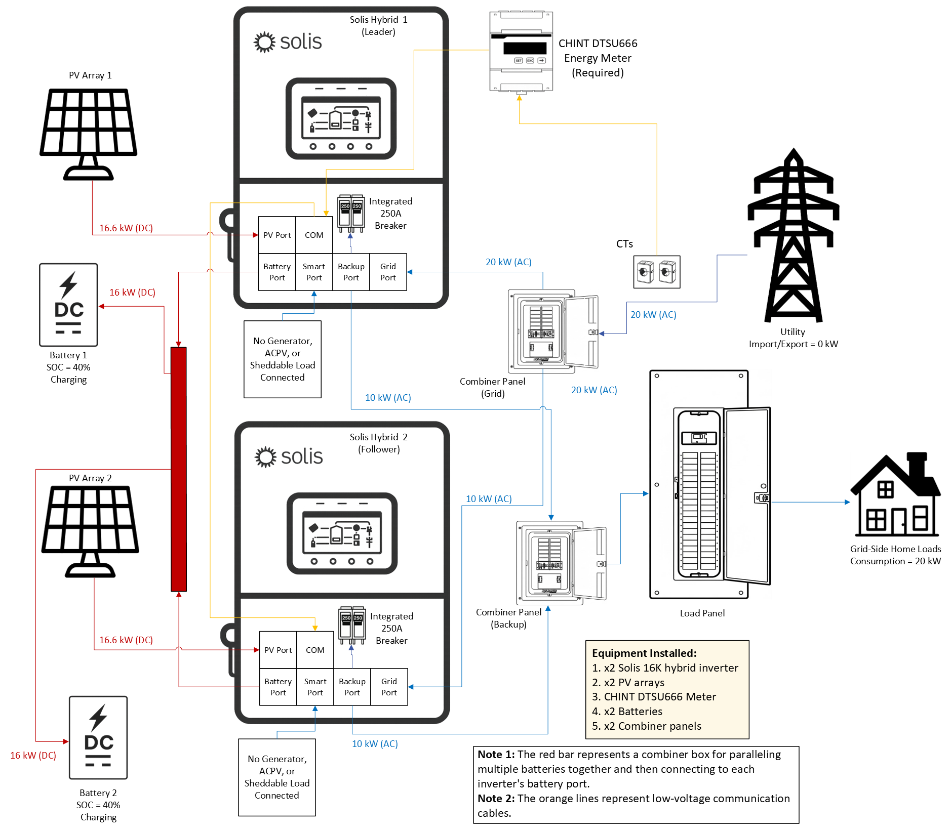
4.7 Paralleling Multiple Inverters
This section is split into two parts꞉ (1) paralleling the Grid ports and (2) paralleling the Backup ports.
The reason for this split is because there are rules and limitations that apply when paralleling the
Backup ports together that do not apply if only the Grid ports are paralleled together. Paralleling
multiple inverters together entials connecting the Grid ports of multiple inverters together in paralelled
breakers within a combiner panel. The same can be done for the Backup ports, but in a different
combinerpanel. Both the Grid and Backup Ports can be paralleled as long as separate combiner panels
are installed. When using multiple batteries, all units must be connected to a common external busbar
before being distributed to the inverters. This ensures balanced voltage and equal current sharing
across the entire system. This applies to both paralleling the Grid ports and paralleling the Backup ports.
4.7.1 Paralleling Only the Grid Ports of the Inverters (No Backup Ever)
If the objective is to utilize this inverter for on‑grid energy arbitrage (peak shaving, time‑of‑use, etc.)
and not use the grid‑forming (backup) function, then only the Grid ports of the inverters will be
paralleled together. The Backup ports will not be used in this type of configuration. When using the
inverter in this manner, there is no limit to how many inverters can be connected together. All of the
inverters in the system will synchronize with the grid and will charge/discharge evenly to meet load
demand. One meter and set of CTs can be used for all of the inverters as long as the inverters are all
daisy‑chained together with communication cables as explained in Section 5.12.5
If multiple batteries are connected to
paralleled inverters, they must all be the same
brand, same model number, and same size
kWh capacity. It is not possible to install
batteries of different brands, models, and
sizes in the same system. This rule applies
both to paralleling only Grid ports and to
paralleling Backup ports. Similar inverters
have this same requirement, it is not unique
to Solis.
4.7.2 Paralleling the Backup Ports & the Grid Ports of the Inverters
Paralleling the Backup ports of the inverter increases the amount of capacity the system owner can
utilize when the grid fails or if there is no grid (off‑grid systems). However, paralleling the Backup ports
carries some restrictions, rules, and limitations that must be followed in order to ensure reliability,
safety, and warranty integrity. These rules, explained in Section 4.7.3, apply when paralleling the
Backup ports of the inverter and do not apply if only the grid ports of the inverter are being paralleled.
This is because the inverter does grid‑forming on the backup side and that requires tight
synchronization between the inverters in order to properly balance power, maintain a stable microgrid,
etc. If you are not paralleling the backup ports please skip this section and ignore the rules listed below
as they do not apply to your system if you are paralleling the Grid ports only.
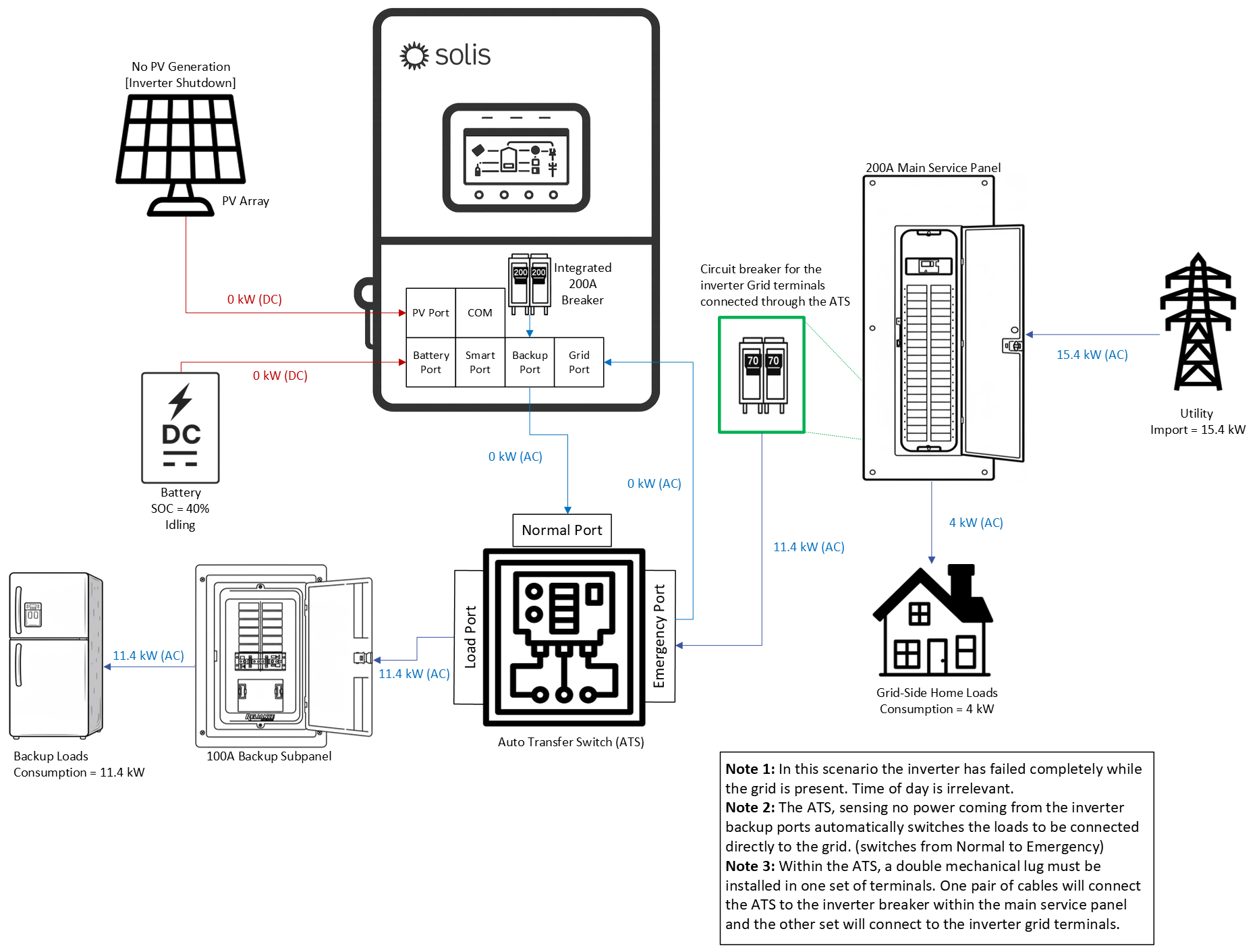
4.8 Using an External ATS to Protect the Loads
A hard fault could be a component failure, thermal event, or other kind of hardware‑related issue that causes a serious malfunction. In this case, the loads connected to the backup side may lose power. If you cannot risk the home ever being without power then it is recommended to install an external third‑party autotransfer switch (ATS). This way the home loads will be protected even in the event of a catastrophic inverter failure. The diagram below shows how an external ATS in the system to ensure that the home loads get power from the grid no matter what happens to the inverter/PV/battery.
Was this article helpful?
That’s Great!
Thank you for your feedback
Sorry! We couldn't be helpful
Thank you for your feedback
Feedback sent
We appreciate your effort and will try to fix the article