Every inverter from the Solis S6-EH2P(9.6-16)K-SV-YD-L-US includes a set of CTs in the same box as the inverter. The model number for these CTs is CHINT NCTK-24 and the CTs themselves are rated for 250A/50mA. It is possible to use a different brand of CT in case the CTs included got lost. However, the rating of 250A/50mA must be the same.
For videos on Installation and Troubleshooting please scroll to the bottom of this article.

1. Pre-Installation Checklist and Reasons for Needing an Optional Meter Kit
Maximum System Current: The standard Current Transformers (CTs) provided are rated for 250A. These CTs are designed to function correctly only if the maximum current flowing through the monitored conductor remains at or below this 250A limit. For installations involving higher current levels, 600A and 1000A CTs are available as optional accessories and must be purchased separately in one of the two available meter kits.
Distance to Utility Point of Common Coupling: The CT wires are 194” (16.16 feet) long and cannot be extended. If the inverter must be installed further away than the CT wire support, the CHINT meter must be installed and connected to the inverter with RS485 instead. However, if all of the system loads are on the Backup port then the CTs can be installed within the inverter wire box around the L1 and L2 Grid conductors.
Large Conductors: If the service entrance uses large-diameter conductors, multiple cables per phase, or irregular busbars, the rigid standard CT may not physically fit. In these scenarios, an optional meter kit including the 1000A-rated flexible CTs (Rogowski coils) is required. These flexible, rope-like sensors can be wrapped around conductors of almost any size or shape, providing a versatile solution for high-amperage systems or crowded electrical panels where space is limited. This kit ensures the inverter maintains accurate power monitoring for self-consumption and export control, regardless of the physical constraints of the site.
2. Optional Meter Kits - Sold Separately by Solis Distribution Partners
Please see the External Energy Meter article for more details on the CHINT DTSU666 meter sold separately.
Standard Meter Kit
SKU: CHINT DTSU666
Included Components: x2 CTs rated for 600A/5A and x1 CHINT DTSU666 meter
Rogowski Coil + Meter Kit꞉
SKU: CHINT DTSU666 (Rogowski Coil)
Included Components: x2 Rogowski coils rated for 1000A and x1 CHINT DTSU666 meter

Note: No other meter type can be used with this inverter. That includes the CHINT DTSU666-H meter, which is the Huawei version of the DTSU666 meter. The -H version will not work with any Solis inverters as it is specific to Huawei products. If you are purchasing this meter on your own, please be sure it is the CHINT DTSU666 meter without the "-H”.
3. Hardware Installation
If there are loads on the Grid-side and the Backup-side of the inverter then the CTs must be installed on the L1 and L2 conductors at the utility point of common coupling. If all of the loads in the system are on the Backup-side, the CTs can go around the Grid L1 and L2 conductors inside the inverter wire box. The purpose of the CTs is to measure the total power exchange between the utility and the system. This is how the inverter calculates total import and export power as well as consumption power.
Direction: Identify the arrows on the CT. There is an arrow on the side and on the inside of the CT. Ensure the arrows point towards the utility and away from the home/inverter. This is to ensure the CT direction setting can be set to “Forward”. If the arrows point away from the utility, the direction setting must be set to “Reverse”.

Location & Installation: Clip the CTs around the L1 and L2 conductors that connect the grid/utility to the system. If all of the system loads are on the Backup-side of the inverter, the CTs can be installed around the L1 and L2 conductors landing in the inverter Grid terminals within the inverter wire box. Make sure the CTs close completely, you will hear a click sound indicating they are fully closed.

Phase Polarity: It is critical that the Current Transformers (CTs) are matched to the specific phases they are intended to monitor. The inverter calculates power by comparing the current readings from the CTs with the voltage readings at its AC terminals. If these do not align, the system will provide inaccurate data.
L1 Alignment: The "L1 CT" (connected to pins 15 and 16) must be installed on the same service conductor that feeds the L1 Grid and L1 Backup terminals of the inverter.
L2 Alignment: The "L2 CT" (connected to pins 17 and 18) must be installed on the same service conductor that feeds the L2 Grid and L2 Backup terminals.
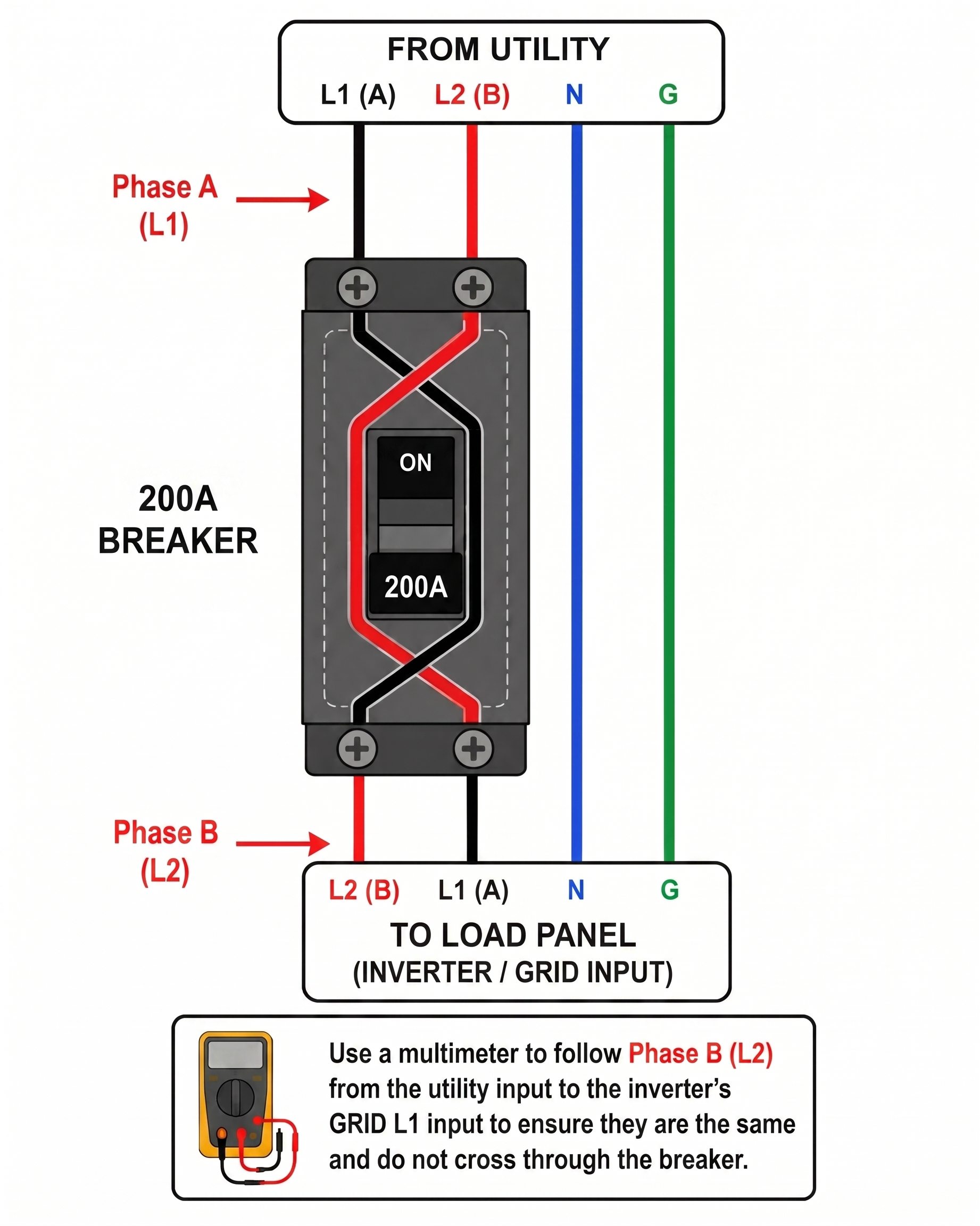
Main Circuit Breakers: Some 200A circuit breakers cross the phases through the breaker so that L1 on the left (or top) becomes L1 on the right (or bottom). It is crucial to check the phase polarity on the load side of the main breaker, not the line side. This small mistake can make be the reason the phases are mismatched.
Consequences of Incorrect Phase Polarity If the CTs are swapped—for example, placing the L1 CT around the L2 conductor—the inverter will measure power abnormally. This often results in the system reporting incorrect values, failing to properly manage export limits, or causing the battery to charge or discharge at inappropriate times. Always verify that the phase being monitored by each CT matches the corresponding AC input phase at the inverter. Use a multimeter on the resistance setting to ring out each phase and ensure they are the same throughout the system to confirm the CTs are on the correct phases.
3. Using a Multimeter to Verify Phase Polarity
In electrical commissioning, this process is often referred to as "ringing out" the wires. Using continuity allows an installer to confirm that the conductor labeled "L1" at the service entrance is the exact same physical wire landed on the "L1" terminal at the inverter.
CRITICAL SAFETY REQUIREMENT: The system must be completely de-energized. Continuity testing involves the multimeter sending a small amount of its own current through the circuit. If the circuit is "live" (energized with utility or battery power), it can destroy the multimeter and pose a significant safety risk.
Steps for Phasing Verification:
Power Down: Turn off the main utility breaker, the inverter AC breakers, and the battery DC disconnect. Use a Voltmeter to verify there is 0V between L1-L2, L1-N, and L2-N at all test points.
Establish a Bridge: At the inverter end, use a jumper wire to temporarily connect the L1 terminal to the Neutralor Ground terminal.
Test at the Main Panel: Move to the service entrance or main panel. Set the multimeter to the Continuity (sound wave) setting.
Identify the Line: * Place one probe on the Neutral/Ground bus bar.
Place the other probe on the conductor you believe is L1.
If the meter beeps (showing a low-resistance path), you have confirmed that this specific conductor is the one bridged to Neutral at the other end.
Repeat for L2: Remove the bridge from L1, move it to the L2 terminal at the inverter, and repeat the test at the panel.
4. Inverter Wiring
The CT wires terminate at the communication terminal block inside the inverter wire box. Simply insert the end of the CT wire into the terminal, no tools are required. To remove the wire, use a small technician screwdriver to open the spring-clamp terminals by pushing and holding the small square button above each pin and then tugging on the wire to pull it out. Once the wires are inserted, give each one a gentle tug test to ensure a firm connection.
Pinout and Wire Colors:
Pin 15: L1 CT+ (White wire)
Pin 16: L1 CT- (Blue wire)
Pin 17: L2 CT+ (White wire)
Pin 18: L2 CT- (Blue wire)

5. Commissioning & Settings
Inverter Settings: Use the SolisCloud app and connect via Bluetooth or use the inverter LCD screen. Go to “Settings” on the app or press Enter on the inverter, down until you get to “Professional Settings” then press Enter or tap “Professional Settings” if using the app. Then go to “Device Setting” and then to “Meter/CT setting”
Meter/CT Settings: Use the up or down button to ensure that "CT Setting” is displayed, then press Enter. On the app, tap “Meter Setting” and then select “CT Setting” and then save it.
CT Direction: If the CT arrows were installed to be pointing towards the grid/utility then the direction should be set to “Forward”. If the consumption data appears inverse or wildly incorrect (e.g., showing as negative), the direction can be electronically reversed by changing the CT Direction setting from "Forward" to “Reverse" instead of physically flipping the CTs themselves.
Location: This should be set to “Grid Side” and if it is not then please change it.
CT Ratio: If you are using the CTs that came with the inverter, then this setting must be set to 5000. If it is set to another value, use the up/down buttons to change it to 5000. Holding the button down scrolls rapidly. The app is easier because you can simply tap the field, enter the value, and then save it.
CT Detection (LCD Only): This setting does not need to be used and does not do anything for the US version of the inverter. Please disregard this setting.
Export Power Control: If an export power limit must be set, this can be done in the Storage Mode settings. To control export power, turn on “Allow Export” and then set a maximum export value in kW. To prohibit export (zero export) then ensure the “Allow Export” setting is disabled.


6. Troubleshooting
Whenever troubleshooting CT issues, it is crucial to use the utility meter values as a baseline reading to compare against. The utility meter is always accurate since it is just measuring direction of power (delivered/received) and amount of power in kW. Comparing the utility meter import/export measurement with the inverter LCD’s import/export measurement is the quickest way to determine the source of the problem. Please see the video below for troubleshooting assistance and installation steps.
Common issues and how to fix them:
LCD showing exactly opposite of the utility meter: If the LCD is showing 4 kW of export but the utility meter is showing 4 kW of import, then the CT direction is reversed. The solution is to either flip the CTs around so the arrow is pointing in the opposite direction that it is currently. Or, change the CT direction setting to the opposite of what it is currently set for. This should immediately fix the problem.
LCD is showing wildly different values from the utility meter: If the LCD is showing much higher or lower values from the utility meter, then it is likely the CT ratio needs to be adjusted. Go to the CT Ratio settings as explained in the previous section and make sure it is set to 5000 if you are using the CTs that came with the inverter (250A/50mA).
LCD is showing approximately half the power or much less than the utility meter: This is likely due to the CT wires being loose or the CTs themselves not being closed completely. Check the CT wiring carefully as per section 4 of this article. Be sure the CTs are snapped closed and are not partially open. Make sure the CTs are in the right place, facing the correct direction, and the wires have not been extended.
Inverter is behaving erratically/abnormally and not abiding by settings: The most likely issue here is the CTs are on the opposite phase (phase polarity issue). Check that the L1 CT is around the same phase as the grid and backup L1 ports. Use a multimeter on the resistance/ohm setting to ring out the phases. If the L2 CT is on the L1 phase and L1 CT on the L2 phase then the system will do strange things and will seem like it is not adhering to the settings at all.
Video: How to Install and Connect CTs Directly to the Inverter
Note: This video was made to be watched on a phone in the vertical orientation.
Video: How to Troubleshoot Common CT Issues
Was this article helpful?
That’s Great!
Thank you for your feedback
Sorry! We couldn't be helpful
Thank you for your feedback
Feedback sent
We appreciate your effort and will try to fix the article