Solis RS-485 / Modbus RTU Wiring Guide
Correct daisy-chain topology, end-of-line termination, and customer installation checks
IMPORTANT: Use dedicated 120 Ω industrial RS-485 cable. Do not use CAT5e/CAT6 for this installation unless a model-specific Solis document and the project design explicitly approve it. |
Correct bus topology and termination
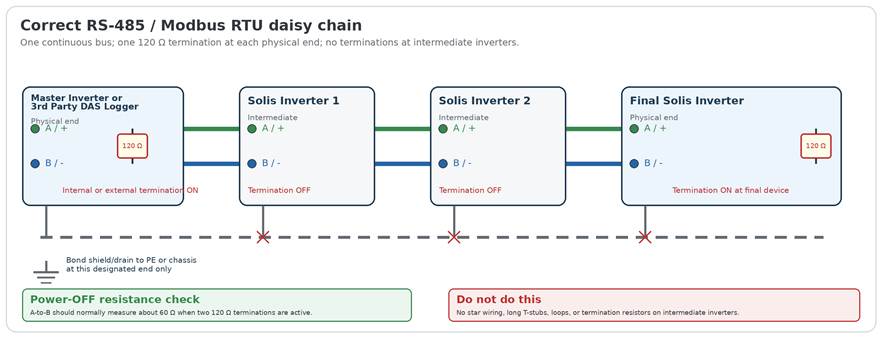
1 Daisy chain only • Run one continuous trunk from the Master Inverter or 3rd Party DAS Logger through each inverter to the final inverter. • Avoid stars, loops, parallel branches, and long T-stubs. | 2 Two terminations total • One 120 Ω termination at each physical end of the trunk. • Intermediate inverters must not be terminated. • A built-in termination switch counts as the termination at that location. | 3 Verify before startup • Power the bus down before resistance testing. • A normal two-end bus typically measures about 60 Ω across A and B. • Verify every device uses the same serial settings and a unique address. |
|
MODEL-SPECIFIC NOTE: Terminal names, connector pins, internal termination switches, and supported device counts vary by Solis inverter and controller model. The applicable manuals remain controlling. | |||
Cable, Shield and Drain Requirements
Use an industrial serial cable and keep the shield continuous through the entire communication chain
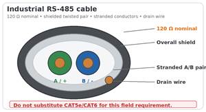
Required communication cable
|
Typical examples: Belden 9841 (one pair) or 9842 (two pair), or equivalent cable with the same required characteristics. |
How to land and bond the shield/drain
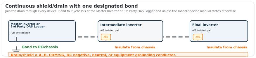
At the Master Inverter or 3rd Party DAS Logger end • Bond the drain to the dedicated shield terminal, bonded enclosure, or PE bar at the designated grounding point. • Keep the bond lead as short and direct as practical. • Do not land loose drain strands on A or B terminals. | At intermediate and final inverters • Join incoming and outgoing drains so the shield remains continuous. • Use an insulated splice, terminal, or shield-through method and keep it off chassis and signal terminals. • At the final end, insulate and secure the drain unless the model manual specifies a shield terminal. |
|
CONDUCTOR SEPARATION: The drain/shield is not A, B, COM/SG, DC negative, neutral, or the equipment grounding conductor. Use a separate insulated conductor when COM/SG is required. | ||
Commissioning and Troubleshooting
Use the power-OFF resistance check and the installation checklist before changing firmware or replacing equipment
Power-OFF resistance check across A and B
Measured resistance | Likely condition | Recommended check |
|
Approximately 60 Ω | Two 120 Ω terminations are active in parallel. | Confirm they are located at the two physical ends and no intermediate termination is enabled. |
|
Approximately 120 Ω | Only one termination is active, or one end is open. | Inspect the opposite physical end and confirm its internal switch or external resistor. |
|
High or open | No termination, open conductor, disconnected terminal, or broken splice. | Check continuity of A and B from end to end; inspect terminal torque and field splices. |
|
Well below 60 Ω | Too many terminations or a partial short across A and B. | Disable intermediate termination switches and inspect for damaged insulation or incorrect resistor placement. |
|
TEST CONDITION: De-energize all communication devices before using an ohmmeter. Internal bias networks or connected electronics can shift the reading slightly. | |||
Installation and commissioning checklist
Electrical and protocol checks ☐ A/+ and B/- polarity is consistent end to end. Verify the actual model-specific labels; A/B naming is not universal between manufacturers. ☐ Each inverter has a unique Modbus address. ☐ Baud rate, parity, data bits, and stop bits match at every device. ☐ Only the two physical ends are terminated. | Cable routing and workmanship ☐ The pair remains twisted until immediately before each terminal and stranded conductors are properly ferruled or terminated. ☐ RS-485 cable is routed separately from AC output, PV DC, transformers, motors, VFDs, and other high-noise conductors. ☐ The drain/shield is continuous and bonded only at the designated point. ☐ Splices, if unavoidable, preserve polarity, twist, shield continuity, and enclosure isolation. |
Before contacting Solis Support
Provide: inverter and controller models, total device count, approximate cable length, cable manufacturer/part number, serial settings, Modbus addresses, power-OFF A-to-B resistance, and clear photos of both terminations and the shield bond. |
Technical basis
• MODBUS over Serial Line Specification and Implementation Guide V1.02 - multipoint trunk topology, line termination near both ends, cable and shield guidance.
• Texas Instruments, The RS-485 Design Guide - twisted-pair transmission lines, termination, stubs, common-mode and grounding considerations.
• Analog Devices, Guidelines for Proper Wiring of an RS-485 Network - termination at both far ends and practical bus wiring guidance.
• Belden 9841 / 9842 product data - 120 Ω industrial RS-485 cable with stranded tinned-copper conductors, shield, and drain wire.
Was this article helpful?
That’s Great!
Thank you for your feedback
Sorry! We couldn't be helpful
Thank you for your feedback
Feedback sent
We appreciate your effort and will try to fix the article