Please follow these steps in order. Read them all the way through before starting, and stop and contact us if anything doesn't look like the photos.
Safety first (do this before opening anything)
Turn the AC breaker for the inverter OFF at the main panel.
Turn the inverter's DC disconnect or PV isolator to the OFF position.
Wait a full 5 minutes for the internal capacitors to bleed down.
Confirm the inverter display is off and the wire box interior is not warm to the touch before proceeding.
Step 1: Open the wire box and remove the inner cover
Remove the screws securing the inverter wire box cover, then lift the cover off and set it aside with its screws in a safe place.
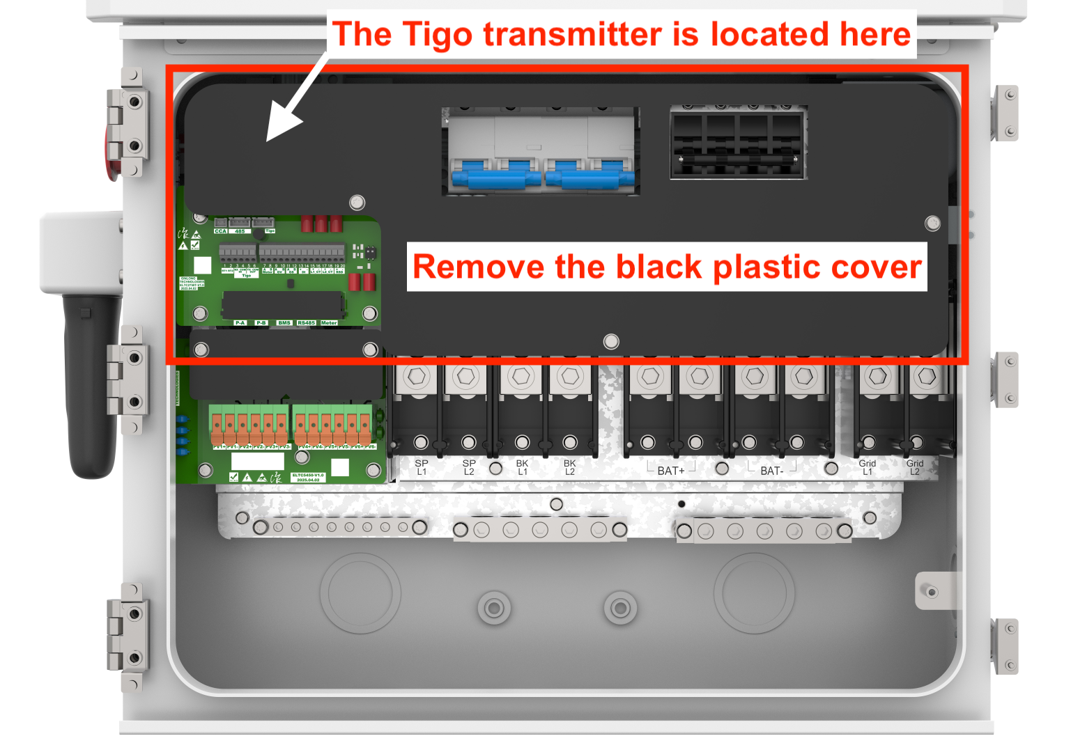
Inside the wire box, locate the black plastic cover mounted above the terminal blocks (it sits over the communication board and the Tigo transmitter area).
Remove the fasteners or release the clips holding the black plastic cover in place, then lift it out and set it aside. This exposes the yellow ribbon cable, the terminal blocks, and the green Tigo transmitter.
Step 2: Release the yellow ribbon cable
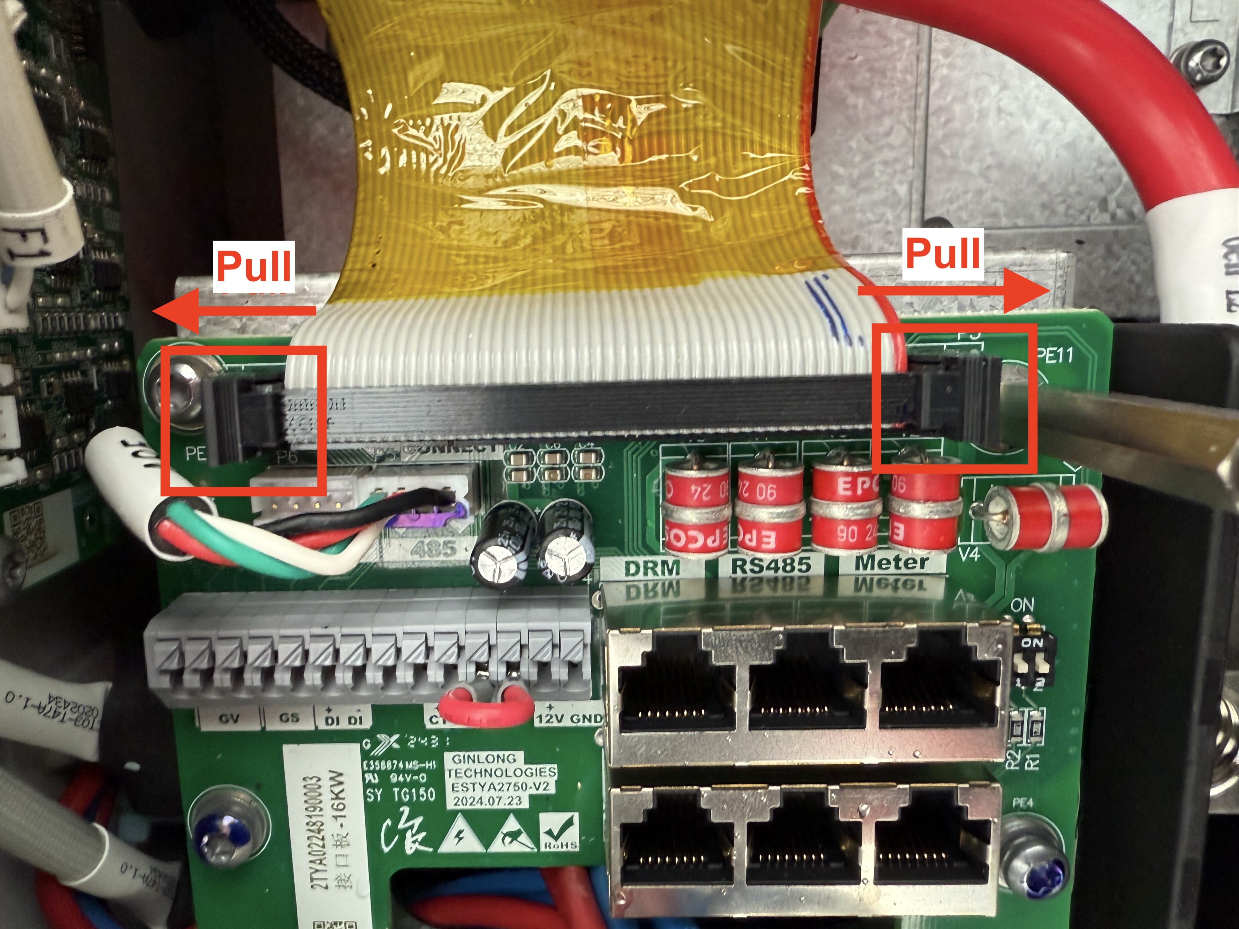
Locate the small black plastic latches on the left and right ends of the ribbon cable connector (shown in the first photo, marked "Pull").
Pinch and pull the left black tab outward to the left.
Pinch and pull the right black tab outward to the right.
With both tabs released, grasp the ribbon cable and pull it straight up and out of its socket. Do not rock it side to side. Pull it straight out so the pins aren't bent.
Set the ribbon cable gently aside. It will be reinstalled at the end.
Step 3: Disconnect the Tigo core wires from the transmitter
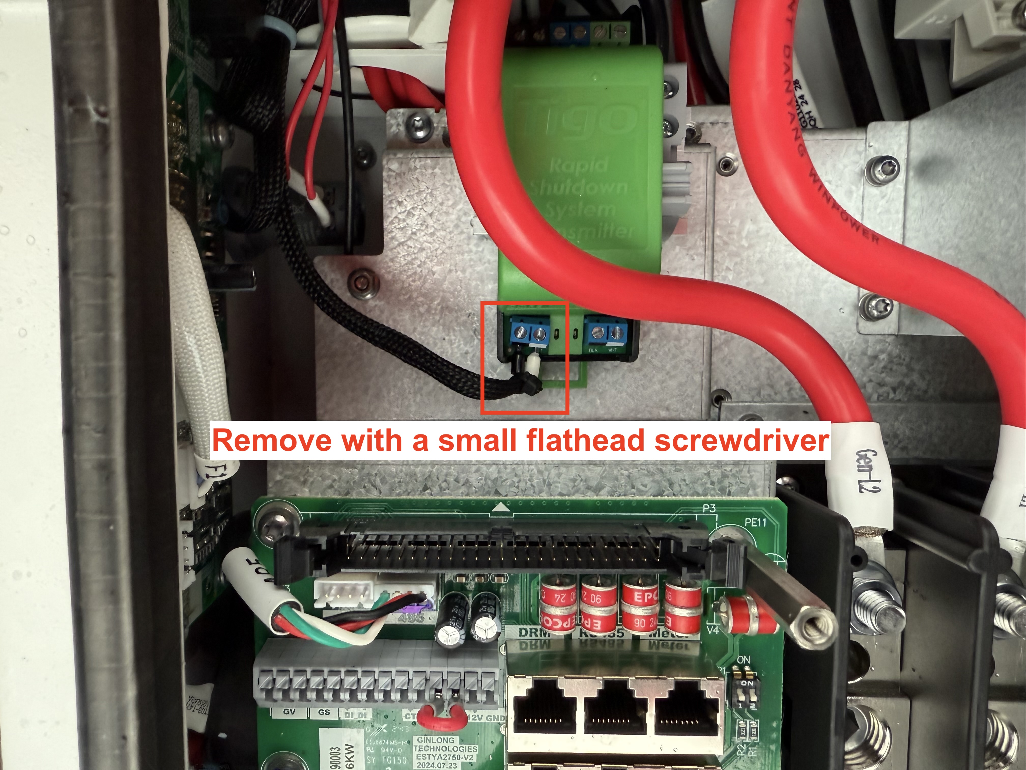
Look at the green Tigo Rapid Shutdown System Transmitter (second photo). The two wires you're removing are in the red box, landed in the two small blue screw terminals on the front of the transmitter.
Using a small flathead screwdriver, turn each of the two terminal screws counter clockwise a few turns to open the clamp.
Gently pull each wire straight out of its terminal.
Wrap the bare metal end of each wire individually with electrical tape so no conductor is exposed, then tape them apart from each other so they cannot touch.
Tuck the taped wire ends into the wire box channel so they aren't resting against the transmitter body or any metal chassis edge.
Leave the terminal screws lightly snug (not tight on nothing) so they don't back out.
Step 4: Reinstall the yellow ribbon cable
Line the ribbon cable up over its socket so the connector keys match the orientation it came out in (the yellow film side should face the same way it did before).
Press it straight down evenly across both ends until you feel the black side tabs click inward and latch on their own.
Confirm both black tabs are fully seated flush against the connector body. If one side is still popped out, press that end down until it clicks.
Step 5: Close up and verify
Reinstall the black plastic cover over the communication board and secure its fasteners or clips.
Reinstall the wire box cover per the inverter manual, torquing the cover screws to spec.
Restore power: DC disconnect ON first, then AC breaker ON.
The inverter should boot normally. With the Tigo core disconnected, the transmitter is no longer sending the keep alive signal.
Was this article helpful?
That’s Great!
Thank you for your feedback
Sorry! We couldn't be helpful
Thank you for your feedback
Feedback sent
We appreciate your effort and will try to fix the article